 |
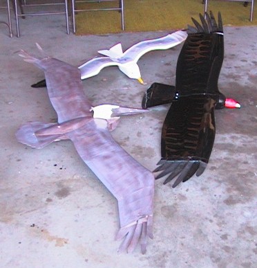
This is a shot
of all
three "birds" that Bob talked about at the meeting. They are the
Pelican, Seagull and Turkey Vulture. He also laid the ground work
for these by covering what the team had found out using their Raven
model,
which can be seen in-flight in the picture below provided by Bob.
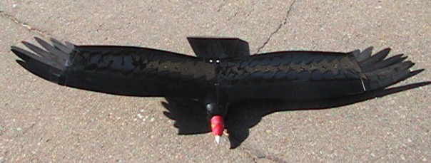
You can see the almost standard configuration for the "tip feathers" used on all but the Seagull. We have closeup pictures of these below, so don't try to strain your eyes. |
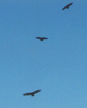
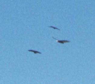
| The pictures below, provided by Bob, show the Turkey Vulture model being flown in a group of real ravens. In the picture directly below, the model is at the bottom of the stack and, in the picture to its right the model is in the middle of stack. Bob commented that he has never seen a raven attack or try to touch one of the models, although they seem to enjoy watching them as a curiousity. |
 |
 |
 |
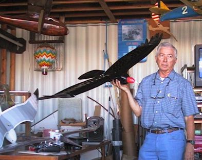 |
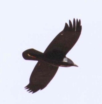
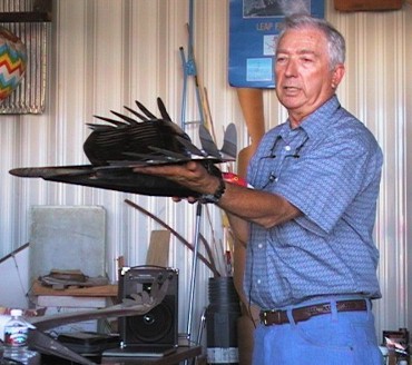
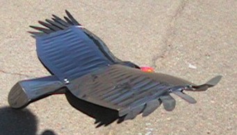
Here is Bob holding up the Turkey Vulture model. You can see that it includes a nose section simulating that of a vulture's head to add to the realism, which may be one of the reasons the ravens weren't afraid to fly around with it. After some initial tweaking of the tip feathers and wing, this has become a good flying model. |
 |
|
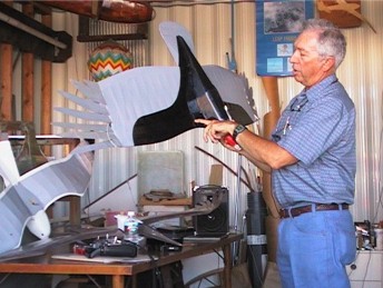
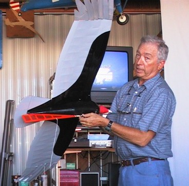
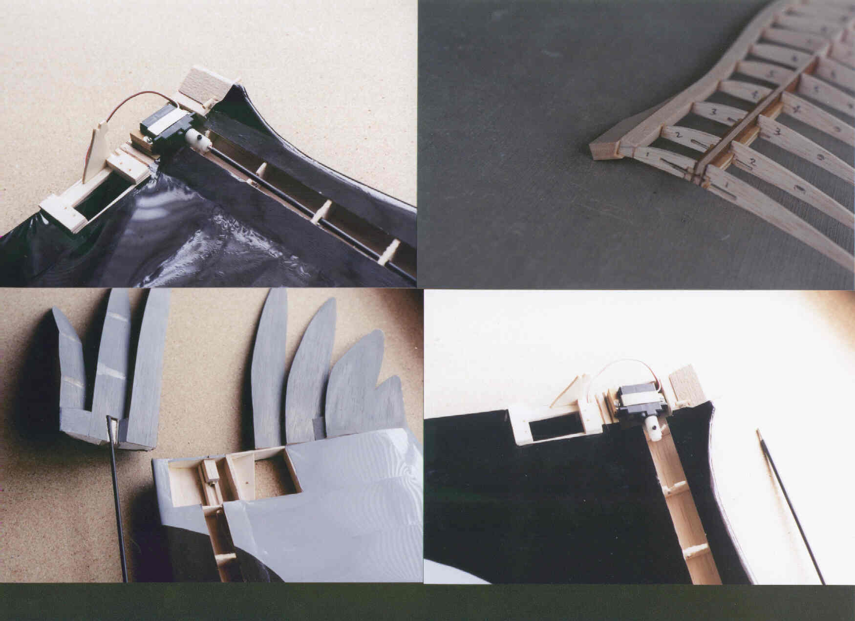
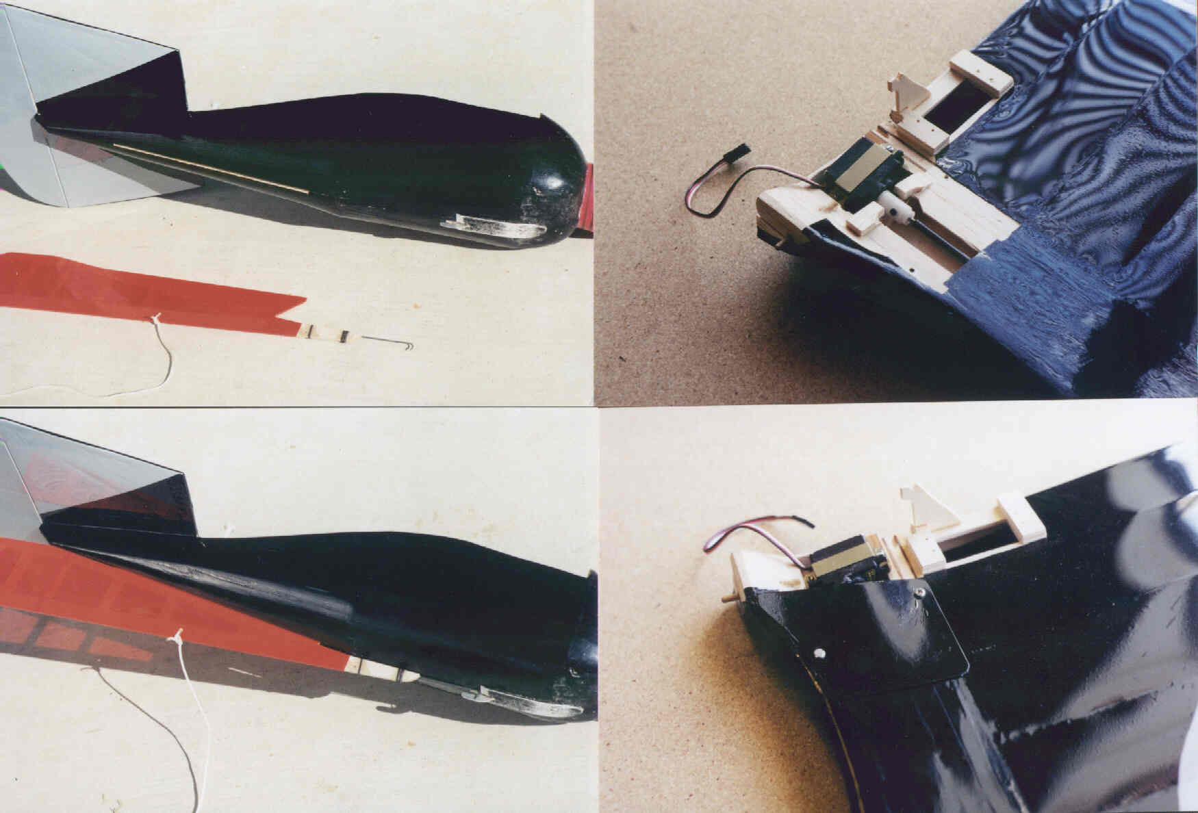
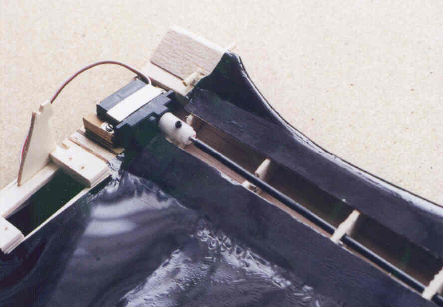
| Right, Bob is showing us that the aileron servo is now mounted on the inboard end of the wing. It uses a carbon rod connected directly to the servo and control surface to move it. It was possible with the straighter wing of the Vulture. This differs from having a servo out by the tip like on the cranked wings and has resulted in less control slop. In the picture below Bob is demonstrating the movement of the control surface and, you can get a look at the way the feathers are spread. These have been found to be the optimum angles. |
 |
 |
|
 |
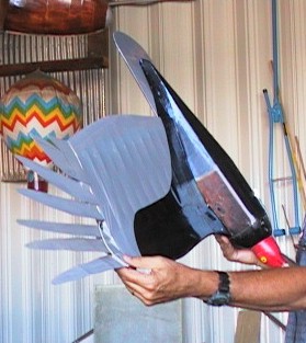
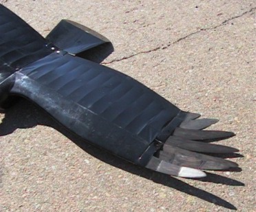
Left, the lead feather is set at
negative 27
degrees (this is not a typo), the second is at -19 degrees, the third
at
-15 degress and, the remaining stationary feathers are reduced 4-5
degrees
per feather until the aft one is at zero. Other combintions of
angles
have not worked as well as this one.
Below, Bob is showing how the high start stabilizing fin is installed in a slot in the bottom of the body. When the tow line disconnects, it also pulls the fin out of the slot so the model becomes tailless again. This fin was found necessary to prevent oscillations on tow that couldn't be controlled with the available aileron authority. |
 |
|
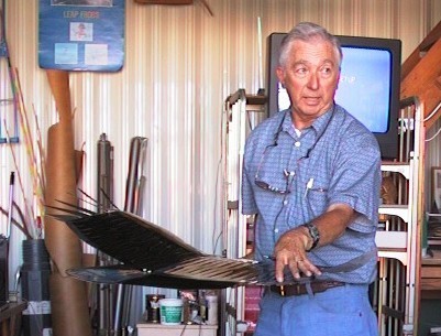
| Right,
Bob is
explaining that the tip feathers need to be spread out, which is the
way
the birds have them during certain times of flight. In some birds
these overlap slightly and actually create an under cambered airfoil.
Below is another shot of the tip feather configuration showing the lengths of each one as they progress towards the rear. Below right, you can see the elevator deflection. This is a two-channel model, although there is a channel used for mixing the ability to adjust the aileron's trim position simultaneously. This was one of the ways they found the optimum angle for the feathers. |
 |
 |
 |
|
.....The
construction article was printed in the June, 2002 issue of Model
Airplane News. Some of the photos and descriptions were not included in
the article.
.....Attached
is the full text of the construction article and most of the photos.
That should allow you to complete the model successfully.
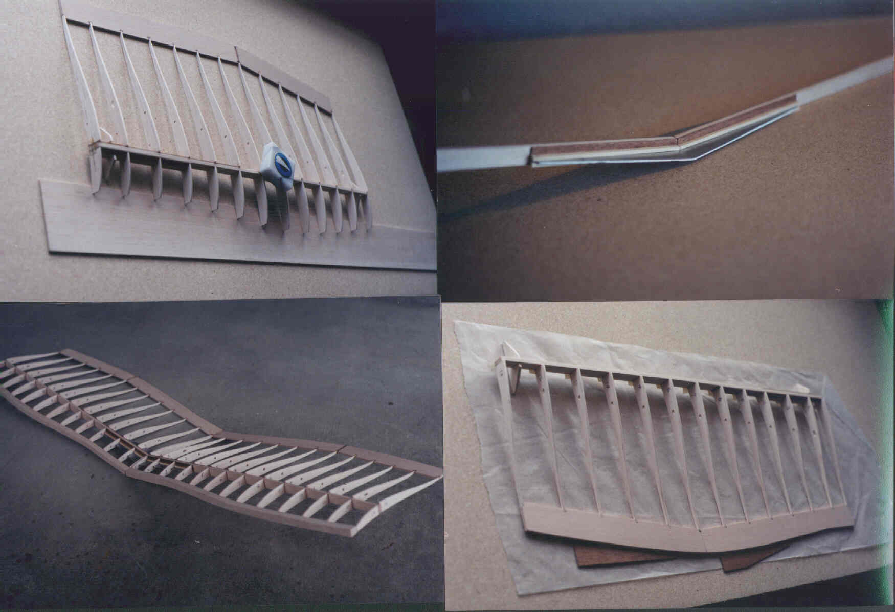
.....The
wing was built with a full-depth spar for added strength since it is a
very thin airfoil. That results in the use of shim blocks to maintain
the desired camber in the airfoil and alignment during wing assembly.
.....It
is a nice flying airplane, but there is one change which I have found
that improves the handling qualities. Reduce the wing dihedral
from 16 degrees (total, 8 degrees per side) to 10 degrees (five degrees
per side). This makes the airplane less oscillatory in roll. Many
builders have also built the wing in one piece which eliminates the
rather complex joiner plate at the wing root.
|
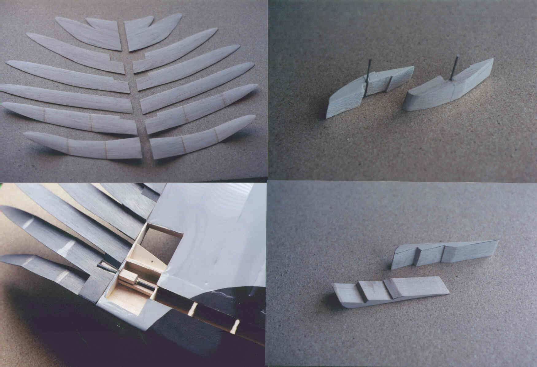
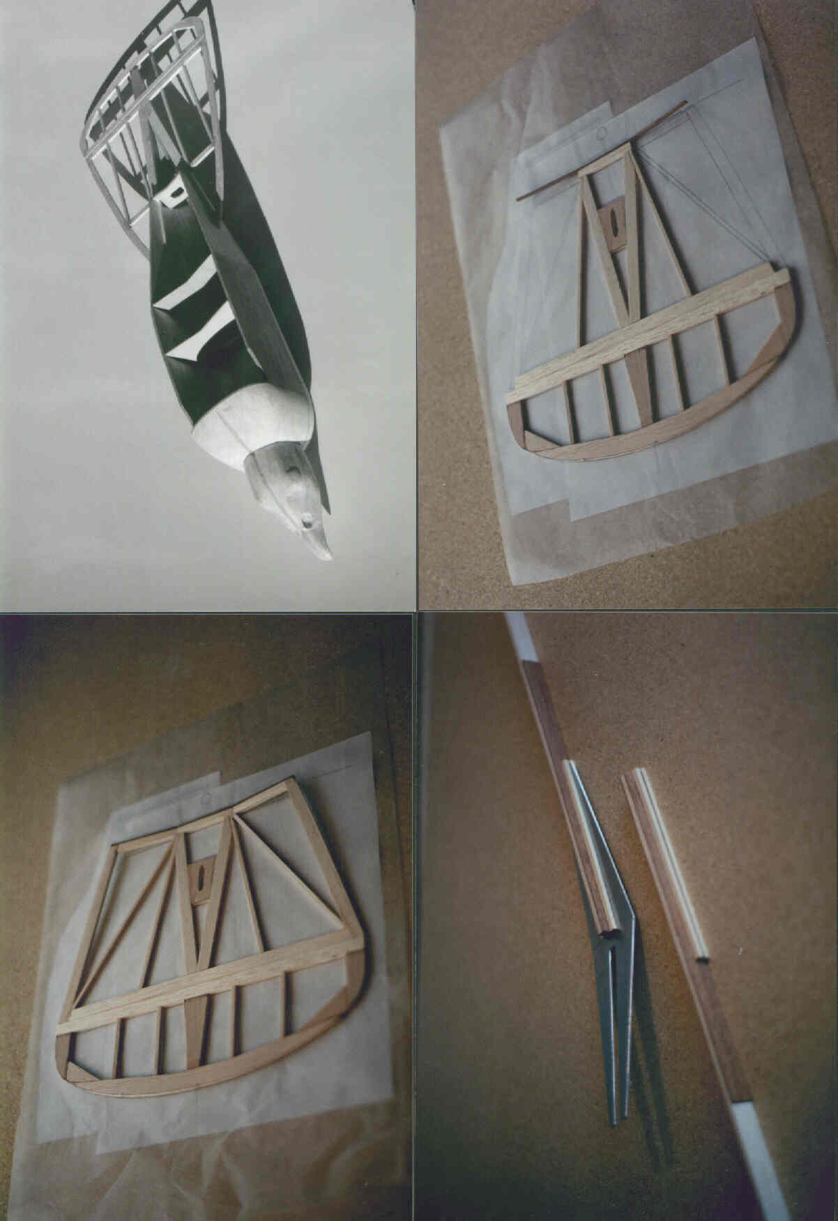
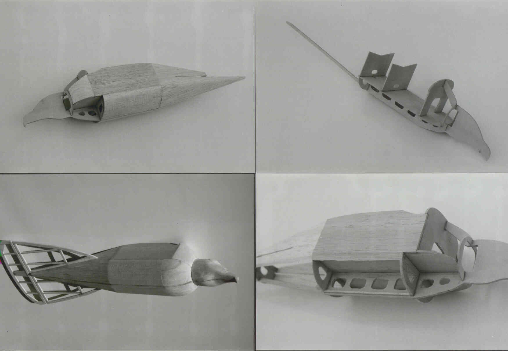
Click on the links below
to open up the construction article and images of the process provided
by Bob. Construction Article Photo #1 Photo #2 Photo #3 Photo #4 Photo #5 Photo #6 Photo #7 |
|
Part 2, The Seagull... |
|
| ...... |
|