|
|
|
(The following was offered by Chuck Bixel of Fort Walton Beach, Florida. If you are interested in discussing any of his observations or conclusions, he can be reached at: cbixel@cox.net) As an old retired military and commercial aviator, aero-marine designer, and itinerant lover of winged flying machines. I recently savored the feelings of being rewarded for my lifetime devotion and a little proud of hopefully discovering an unusual aerodynamic design concept that fulfills some of the less understood theories of flight. I believe, the standardization of aircraft designs while, unconditionally required for world wide operations and manufacturing, has become a detriment to free thought and wonderment of the mysteries of flight. To unravel and understand a differing concept of flight with practical applications is fulfilling. As simply as Im able, Id like to tell of my experiences with flat/ symmetrical airfoils and non standard wing shapes leading up to my findings. A couple of decades back the, (60 Minutes TV show), produced a presumably humorous fill in story about a young millionaire. He had invested about five grand to compile and publish a book on how to make folded paper gliders. One year later, he had become a millionaire. Our TV program illustrated some of the designs and showing him in a plush high rise office flying his paper gliders. Proof that, with a little ingenuity, thought, and risk, the get rich opportunities still abound. I had bought his book as, Im sure a lot of us did. Surprisingly, two weeks later, the young entrepreneur was back on the, (60 Minutes TV show). 60 Minutes reported they had never received such an enormous mail response from any program they had ever produced. Most inquiries were about, how and why, the small paper gliders could be so stable and efficient in both, upright and inverted flight (always returning to level flight no matter how badly launched). Also, why didn't some modern aircraft use the designs? I'm sorry to say it but, no one could answer that question. The show had interviewed an engineer from NASA, who had honestly admitted not knowing the answer. They also had interviewed a senior aeronautical engineer assigned to Wright Patterson AFB. He bumbled on, saying that he thought, it had something to do with the double layer of folded paper on the underside of the gliders wings. He exhibited a small standard airfoil aircraft model with a notched out portion of the under wings surface, (speed boat/pontoon stepped hull form type or somebody forgot to install the flaps on), for illustration. I built a small styro-foam glider model as illustrated and promptly found out, the under wing notches only degraded the model gliders flight performance. Copying the paper glider wing profiles, I cut three different large glider wings from one inch thick styro-foam sheets. These larger wing area gliders had lengths up to eight ft. and wing spans of four ft., six ft, and eight feet. We played with the gliders on and off for weeks, experimenting and fine tuning their balance and rudder areas. Trying to better understand the nature of their unusual flight characteristics. We, (mostly old military and airline pilot friends), were able to fine balance the gliders until, very little or no pitch control or elevator trim control was needed for safe flight. We determined; 1. The properly balanced flat airfoil tail less, (no elevator), paper glider type wing profile designs flight characteristics and performance were roughly identical upright or inverted. 2. FLAT AIRFOIL FLIGHT CHARACTERISTICS. The Low and very Low Aspect Ratio Flat Airfoil Gliders Lift performance does not increase or decrease with airspeed changes like standard airfoil wings. Catapult launched at very high relative speeds the gliders flew perfectly straight and level tracks. The gliders slowly increasing their initial minimal flight angles as they decelerated, compensating for the decreasing flight speeds loss of lift efficiency. The paper glider type flat airfoil wing profiles characteristically produce only the minimal lift required for level flight over their full speed range. When launched at a fifteen to twenty degree climb angles the gliders flew straight tracks while decelerating to their normal glide speeds where, the flight angles smoothly decreased to their typical glide angles and they glided back to the surface. Higher launch angles, (45 + deg.), produced typical stall characteristics, generally followed by high angle dives back to the surface. When the gliders stall recovery nose down angle was minus fifteen degrees or more it would remain at that nose down angle accelerating until contacting the surface. At stall recovery angles less than minus fifteen degrees the gliders normally corrected their decent angles for normal glide performance. The normally slower glide speed characteristics and flight efficiency, (glide ratios), of these large flat airfoil design gliders appeared to be as high as, and maybe even a little higher, than standard high performance R/C model sail planes. The largest foam glider built with the lowest wing loading exhibited some not before seen stall characteristic. This model when launched at a fifteen to twenty degree nose high angle would decelerate along this track angle until it fully stopped in mid air, it then slowly flew/slid backwards-downhill for about six feet while, the nose gently lowered to its preferred glide angle, reversed direction again, resuming normal forward gliding flight. This light weight foam models glide speed was unusually slow, (about five mph), reminding one of floating balloons or a gliding butterflies flight, just wobbling along reacting to the mixing light air currents. Adding lead weights to the gliders CG position produced compensating glide and stall air speed increases. 3. Reviewing my old 1948 airfoil catalogs, I searched for any major differences between the Cambered and Symmetrical airfoil flight performance data. I first discovered a number of symmetrical airfoils so thin there was no reason not to call them flat airfoils. I remembered that, back in those days they taught us to never use flat airfoils in our designs. I don't recall the exact reasons however, I do recall that Flat Airfoils were only supposed to be used as a standard base line for determining cambered airfoil wind tunnel lift and drag data. Reviewing the airfoils as types, it was evident that the majority had nearly matching Lift/ Drag curves and values. The values essentially being relative to their airfoil thickness ratio. The typical cambered airfoils normal flight angle range is from -4 degrees to +12 degrees while, the flat airfoils flight angle range is from +0 degrees to around +27 degrees. The cambered airfoils most efficient flight angle is in the one to two degree flight range and the flat airfoils best flight angle is always close to four degrees. Comparing both airfoil types with, the same thickness ratios, the flat/symmetrical airfoils Lift/Drag values exceed the cambered airfoils values by nearly ten percent. Many of the cataloged symmetrical airfoils reviewed had much lower thickness ratios than the cambered airfoils. Comparing a thinner (5 %) flat/ symmetrical airfoil to a standard (12 %) thickness ratio standard airfoil indicated a marked improvement in its cruise flight efficiency. The main difference between the two airfoils is their reversed Aerodynamic Center of Lift, (CP), travel directions and response characteristics. I dont pretend to understand why their CP travel directions are reversed however, this is the major defining difference in their general flight characteristics. The typical cambered airfoils CP travel ranges are from near 20% to 100% of its wing chord. Traveling full aft rapidly as the airspeed increases above design cruise values and the Angle of Attack decreases to minus values. The low Aspect Ratio cambered airfoil with a larger wing chord produces correspondingly increased CP travel distance and reaction forces. Greatly increasing the pitch up or pitch down forces at its performance envelopes minimum and maximum airspeeds. Low AR., (short wing spans with large wing chords), cambered airfoil designs require larger tail control surfaces, and or longer tail moment arms to control the CPs increased forces and travel distances. The flat airfoil charts show its CP travel characteristic are reversed to the standard airfoils. The flat airfoil CP remaining nearly stationary, (slowly creeping aft), from high speed to normal cruise flight angles. During slow speed high angle, (+ 15 to + 26 deg.), flight the CP rapidly moves aft to reduce the angle of attack and resist stalls. The reversed CP travel direction and differing flight reaction characteristics are the primary reasons, all flat airfoil aircraft posses strong level flight stabilizing characteristics. Notes: a. Standard airfoil catalogs only report
wind tunnel performance data for small model wings with Aspect Ratios of
6 to 8. ( I would really love to see some charts for some very low
AR cambered and
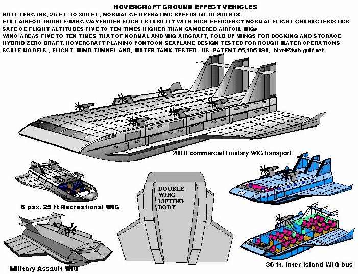
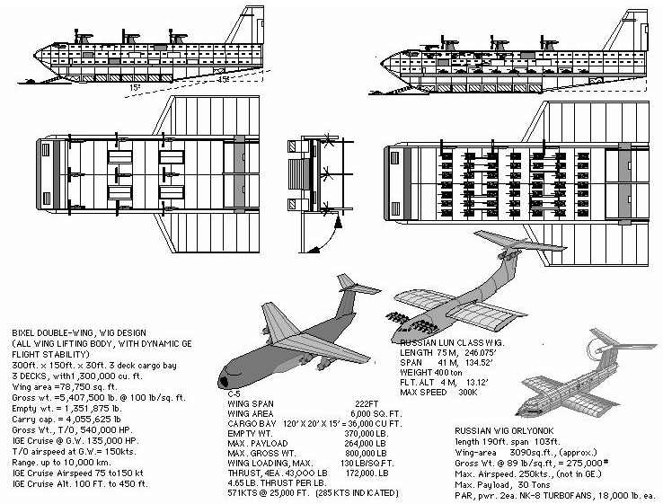
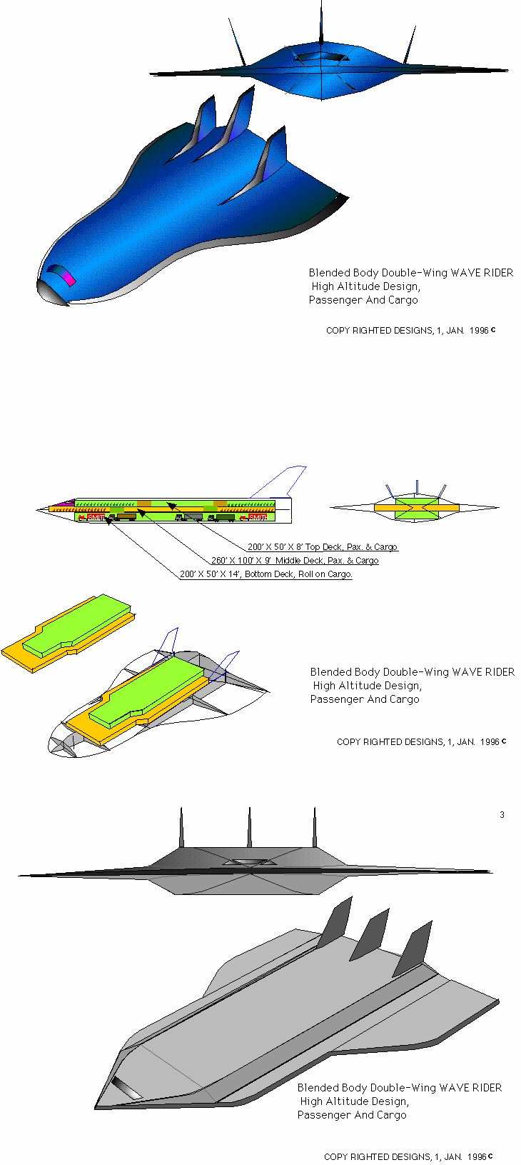
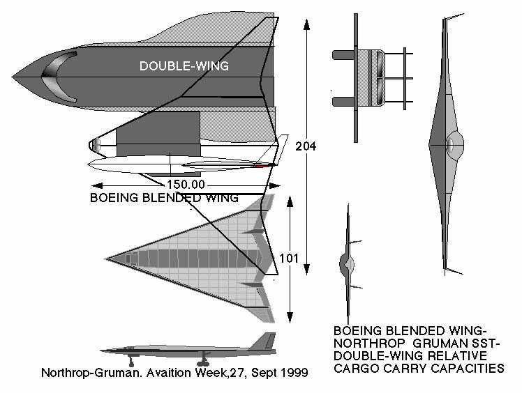
b. The barely flying light and ultra-light aircraft have such low airspeed envelopes that the cambered airfoil CP travel problems may barely exist. 4. WING IN GROUND EFFECT FLIGHT PROGRAMS. The past and current concepts of shortening the wing span and increasing the wing chord of standard airfoil WIG aircraft designs has yet, to improve the aircrafts flight efficiency in or out of WIG flight. The WIG aircraft's increased pitch sensitivity, loss in flight efficiency, and the obviously dangerous low level flight altitudes required leaves few WIG aircraft crash free to have normal life spans. Doubling the wing chords length proportionally doubles its CP travel distance requiring, greatly increased area horizontal tail/canard high drag pitch control surfaces and longer not shorter tail moment control arms. However, Increasing a flat airfoils wing chord five to eight times proportionally improves its already exceptional flight stability. The increased CP travel distances produce flight leveling forces of sufficient strength to maintain established GE flight angles that produce WIG wave rider flight, allowing hands off WIG flight control. Some current flat airfoil WIG designs have increased wing/lifting body design layouts with, up to ten times the effective wing area of the short wing span WIG modified standard aircraft wing area and airfoil designs. The larger wing areas produce proportionally increased aerodynamic lift and increased volume GE reaction cushions. The increased volume and depth of the GE cushion allows WIG flight altitudes ten times higher than any current WIG designs. Only the very low AR flat airfoil WIG designs have produced WIG aircraft capable carrying many times the volume and weight of our largest modern cargo aircraft. The design has the operational probability of only requiring half the aerodynamic lift required for normal flight when riding on the GE cushion. Unlike, most pervious WIG modified standard aircraft designs that produce only a very small speed envelope, (sweet spot), for GE flight. The flat airfoils GE performance extends over its full air speed range. The increased wing area, lighter structured, and reduced wing area loading, flat airfoil designs also provide increased normal flight altitudes, flight efficiencies, and lower take off speeds. The Double-Wing Lifting body WIG designs performance is similar to most Flying Wing designs. Like the Flying Wing it is all lift but, without the aerodynamic Lift/Drag consequences from the wings span wise twist designs, and high speed flight limitations. The Double-Wing Lifting Body design is fully capable of going into more economical true flight to over fly land masses for access to inland rivers and lakes. 5. The design concepts for symmetrical airfoil Delta and Double Delta larger wing area high altitude mach II and mach III reconnaissance and airline aircraft are well established. These aircraft while being, super fast, are undeniably not efficient. They use their tremendous power and increased wing area to reach exceedingly high altitudes and flight speeds. However imagine, how much more flight efficient a lighter structured, non-pressurized WIG SEAPLANE with ten times the lift capacity of the worlds largest standard aircraft could be if it produced half the aerodynamic lift required for normal flight from its Ground Effect reactions. (Comparison of Boeing BWB, Northrop/Grumman and WIG configurations.)
|
|
|