(NOTE: This was a paper
written by Don
Mitchell (year unknown) and provided to TWITT by
Richard Avalon of U.S.
Pacific, a distributor of Mitchell B-10 and
U-2
plans. It is a unique perspective on how Don
thought about the use
of flying wings. For those interested in more on
Mitchell designs, visit the Mitchell Wing website:
https://mitchellwings.com/.
Also
see his mini-autobiography.)
DON MITCHELL SHORT BIO
Don
Mitchell is a
veteran of the aviation industry, thoroughly trained
and schooled in engineering
and construction.
He has
co-designed and
built four of the outstanding sailplanes and power
gliders in the country.
He has
gone through
the “N.C.” procedure for approved type certificate for
aircraft on seven
occasions and knows the workings of the Civil
Aeronautics Administration
as well as many of the men in it. (ed. - This gives
some idea of the time period.)
Any
references or additional
information regarding Mr. Mitchell’s background are
available upon request.

INTRODUCTION
The
National Air Races
held annually at Cleveland, Ohio are a thrilling air
show a valuable source
of aircraft improvement.
In 1946,
to encourage
the design and development of light aircraft the
Goodyear Tire & Rubber
Company created and spon-sored the “Goodyear Trophy
Race” as part of the
National Air Races.
This
booklet is submitted
in a sincere effort to obtain a sponsor and co-owner
for the racer herein
described. It is a project that vigorously breaks away
from the exhausted
conventional design.
It is
not, however,
a flight of the im-agination, but rather one based on
sound advanced aerodynamics
with practical data proving this type of aircraft is
without parallel.
It is a
project that
not only will admirably perform its main purpose of
winning races, but
one that can be used as a nucleus for the design of
cheap, safe, high performance
light aircraft, military pilotless jet drones, target
ships, and practical
roadable airplanes.
The
reader will recognize
within these covers the outline of a project that will
have an immediate
satisfaction and profit to the sponsor, designer, and
to the aircraft industry
as a whole.
DSM
SPECIFICATIONS
Top
Speed
245
M.P.H.
Landing
Speed
55
M.P.H.
Engine
Continental
C-85
85
H.P. at 2570 R.P.M.
Pusher Installation
Span
18
feet
Area
72
Sq. Feet
Sweepback
40
Degrees
Total
length
9
Feet
Nacelle
height
43
Inches
Weight
empty
400
lbs. **
Ballast
100
lbs. **
Landing
Gear
Tandem
(Two Goodyear tires and wheels- 5.00-5)
Brake on rear wheel
No dihedral. No wing twist.
**
500 lbs. minimum weight empty required for Goodyear
Race.
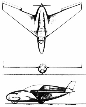
CONSTRUCTION
MATERIAL:
Sitka spruce spars and ribs.
Three-ply plastic
bonded mahogany plywood skin.
Molded plastic bonded mahogany
semi-monocoque
pod (nacelle). Plexiglass bubble canopy.
This airplane meets all of the
regulations and
requirements for the Goodyear Trophy Race.
WHY THIS RACER?
Because,
. . . It is ultra modern and
sensational in appearance;
. . . It has sparkling, exciting
performance;
it has the ability to smash records;
. . . It has eye appeal and fires
the imagin-ation
- qualities necessary for wide-spread and
lasting
publicity;
. . . It has the “New Look” in
aviation;
. . . It has terrific
potentialities besides racing;
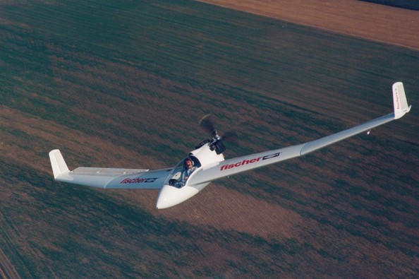
. . . It will be the first flying
wing to compete
in the National Air Races;
. . . It has a basic control
method destined to
bring a new era to aviation.
Winning
races is the
prime purpose of a racing airplane. THIS flying wing
will do that -- and
much more.
It will
bring instant
publicity. Publicity poured out by papers, magazines,
radio and newsreels;
by articles elaborating on the future possibilities of
the ship, its natural
adaptability to civilian light planes, to military jet
drones, to radio
target ships, to roadable aircraft; by articles on the
fantastic simplicity
of the structure, on the safety and efficiency of the
control method.
The
publicity will continue
indefinitely because this racer stimulates and excites
the imagination
with its many wonderful possibilities.
It will
bring lasting
fame and honor to the sponsor for having foresight and
vision to back a
ship years ahead in design.
The
conventional airplane
has been developed to a remarkable degree in the past
fifteen years, but,
it has been apparent for some time now that any real
advancement must come
through a new overall design change; one that
inherently embodies the characteristics
of lower drag, less structural weight, higher
strength, simpler construction,
better blended design, and more compact form.
THIS
PROPOSED RACER
HAS ALL OF THESE CHARACTERISTICS. They
give to the ship more
speed, acceleration, maneu-verability, safety and
lower cost. Characteristics
unobtainable at any price in conventional aircraft.
The heart
of this racer
is the external control surfaces functioning as
elevators and ailerons
(ailevators). Only through
the use of these ailevators
can a compact, rugged, superbly blended design such as
this be accomplished.
Only
through the use
of ailevators can stability, safety, and
controllability be accomplished
in a flying wing without sacrificing any high speed
advantages.
The thin,
swept, cantilever
wing, small cross section nacelle, tandem landing
gear, and advanced cooling
arrangement of the Continental C-85 pusher engine
installation gives this
ship a clear forty five mile per hour high speed
margin over the best racers
built to date in the same class.
The super
compact design
of the ship combined with the ailevator control makes
for lightning and
precision maneuverability. Visibility is excellent due
to the bubble canopy
and the absence of engine or bulky fuselage in front
of the pilot. These
are of the utmost importance in aircraft.
The
tandem landing gear,
aside from being more streamlined, is safer in taking
off or landing. The
center of gravity is so low in relation to the ground
contact points that
nosing over is eliminated even when landing with the
brakes set.
A small skid midway out on the wing keeps the wing tip
up off the ground
in ground handling.
The
pusher engine installation
has better streamlining and higher propeller
efficiency. The engine is
completely enclosed within the beautifully streamlined
housing. Cooling
air is taken in at the leading edge of the wing,
forced around the four
cylinders and ejected rearward through an annular slot
at the propeller
spinner.
A
blower is installed
at the propeller end of the engine shaft for moving
the air through the
ducts. This installation reduces cooling drag by more
than 50% over conventional
methods. The air outlet, besides boosting propeller
efficiency, helps to
control the boundary layer over the aft part of the
nacelle resulting in
a marked reduction of the overall drag of the ship.
THIS RACER WOULD BE THE
FIRST FLYING WING TO
PARTICIPATE IN ANY RACE IN
THE U.S.A.
This
flying wing racer
is not big EXCEPT IN PERFORMANCE total length being
only about nine feet,
span eighteen feet, and the height to top of nacelle a
mere forty-three
inches. This compactness is realized through making it
a flying wing. Its
safety and top performance realized through the use of
the AILEVATORS for
complete and exacting controls at low as well as high
speeds.
The
detailed design
and engineering have been meticulously worked out to a
point where construction
of the actual ship could be started immediately.
Its
spontaneous acceptance
will bring a new, a safer, a more practical era to
aviation.
Will YOU be the sponsor?
THE MITCHELL EXTERNAL
“AILEVATOR”
CONTROL METHOD FOR FLYING
WINGS
Why haven’t there been built
commercial versions
of flying wings? such as:
......................Lightplanes
......................Roadable
Aircraft
......................Sailplanes
......................Executive
Transports
In the
face of the many
basic aerodynamic and structural advantages of flying
wings we still find
that commercial versions are not in existence. Here is
the reason:
All of
the control methods
used to date on flying wings are completely inadequate
and incapable of
meeting the requirements for safe precision control
and stability at both
high and low speeds.
It has
always been a
simple problem to:
.......1.
Make flying
wings controllable at low speeds (high angle of
attack).
.......2.
Make flying
wings controllable at high speeds (low angle of
attack).
But, it
has not been
possible to make the same flying wing safe and
controllable at both high
and low speeds.
The
Mitchell external
“ailevators” solve this basic problem in a simple,
straightforward, efficient,
and direct manner, thereby removing all of the
barriers standing in the
way of practical civilian flying wings.
Ailevators are external
central surfaces much smaller in area than the main
wing. They are located
slightly below the trailing edge of the main wing and
towards the tips.
There is a passageway for free airflow between the
leading edge of the
surface and the trailing edge of the main wing.
Ailevators are not a
part of the main wing. They are independent surfaces
located so that they
favorably influence the airflow over the main wing. At
high and medium
speeds they cut down the drag on the main wing by
smoothing out the airflow
leaving the trailing edge.
The
external surfaces
are used as ailerons and elevators, hence the word
AILEVATORS.
Wing tip
stalling of
conventional flying wings takes place when the ship
attains a moderate
angle of attack. When it occurs, elevator
effectiveness is lost and, as
a result, the ship is unstable and uncontrollable.
Slots, twist (washout),
or change in airfoil toward the tips do help this
condition but do not
conquer it, and in themselves present serious
structural, aerodynamic,
and production problems.
EXTERNAL
AILEVATORS
PREVENT WING TIP STALLING AT ALL ANGLES OF ATTACK
without the use of
any of the complicated stall aids mentioned above.
They do this partly
by controlling the boundary layer over the wing due to
the favorable airflow
between the trailing edge of the wing and leading edge
of the surface,
and partly by lowering aerodynamically the angle of
attack of the wing
preceding the surface when the ship is brought up to
medium and high angles
of attack.
The
technical aspects
of the control method are quite involved and will not
be gone into at this
time, however complete information on the control
system is available.
COST BREAKDOWN
The money required for the
construction of this
shin must and would be kept to a minimum. Naturally
the smaller the in-vestment
the greater the profit in winning races.
The major cost items are:
1. AIR FRAME....................................................................
$60.00
Mr.
Mitchell has on
hand all of the material for the air frame except a
few pieces of plywood.
He has pulleys, cables, rod ends, bolts, tubing and
miscellaneous parts.
2. WHEELS, BRAKES, TIRES...............................................$50.00
For this
racer these
items can be obtained through the Goodyear Tire &
Rubber Company at
cost.
3. MOTOR, EXTENSION SHAFT.......................................$987.00
The
Continental 85 h.p.
engine lists for $787.00. It is not necessary,
however, to use a
new engine, and., if desired, a
satisfactory
reconditioned one may be obtained at considerably less
cost. The extension
shaft is a simple machine shop job and need not run
over $200.00.
4. PROPELLERS...............................................................$800.00
The
maximum performance
of any ship is to a large extent determined by the
choice of the propeller.
This ship, being a pusher installation, cuts down on
the choice of available
propellers. However, the Sensinich Propeller Company
has a wood pusher
propeller design that would be satisfactory to start
with. The cost of
this propeller is $65.00 each. Several other
propellers would have to be
made and tried in flight to obtain the one for maximum
performance. For
this reason $800.00 is set aside for propellers.
5. PLEXIGLASS BUBBLE....................................................$50.00
The
canopy is of simple
design and could be molded by Mr. Mitchell or he could
have it done at
minimum cost through his personal connections with a
leading aircraft plexiglass
molding company.
6. LABOR - SHOP - MACHINERY.................................$3,300.00
This is
a small ship
and the room required for construction would be
minimal.
|