BKB-1
by S. K. Brochocki,
Canadair Limited, Montreal
Presented at the 8th OSTIV Congress,
Cologne, Germany, June 1960
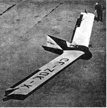
Figure 1
BKB-1
by S. K. Brochocki,
Canadair Limited, Montreal
Presented at the 8th OSTIV Congress,
Cologne, Germany, June 1960
Figure 1
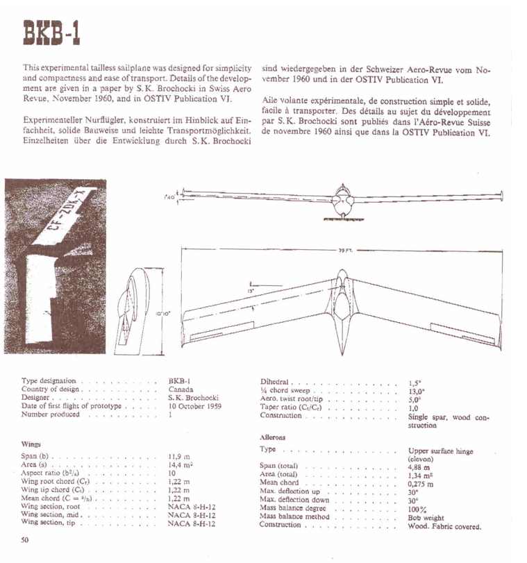
ScopeA single-seater sailplane is presently being flight tested in Canada. This sailplane is a design exercise aiming at a development of an economical glider capable of satisfactory performance. There seems to be a great need of such a machine since, with the exception of countries where the governments provide financial support, the future of the sport lies in the hands of the private owner and impecunious clubs.
Economy is understood here to lie in low purchase and running cost as well as routine handling. There is still plenty of hardship and inconvenience connected with any aspect of rigging, taxiing, retrieving, storage, etc., that offer scope for improvement. It is obvious that reduction of size, weight and perhaps number of structural components, reduce the cost and the handling problems as well.
Geometry for Optimum Performance
Unfortunately, the drastic reduction of size brings deterioration of performance, which must somehow be made satisfactory for the Sunday flyer as well as the contestant. The question thus arises as to what constitutes the optimum and also, what features of performance to aim for.
One should consider performance under various conditions. These include seasonal and daily changes, geographical location and type of atmospheric energy usable for soaring. Most of the sailplane flying is accomplished utilizing thermals which are highly dependable onthe above variables.An article, "What Price Performance?" written by B. H. Carmichael and published in the May-June, 1954 issue of Soaring offers a well substantiated study of the problem. The author expresses performance in terms of cross-country speed. Sailplanes capable of high cross-country speeds possess well-balanced characteristics consisting of good rate of climb in thermals, and penetration, permitting fast flying with small loss of height. The study results in somewhat surprising conclusions with regard to optimum aspect ratio. Quoting the article:"For both the strong and the weak thermal of what is believed to be normal diameter, the optimum aspect ratio is surprisingly low. It increases from the order of 7 at the 30 foot (9,1 m) span to about 20, at the 90 foot span (27,5 m). Consideration of the strength of the thermal did not change the choice of optimum aspect ratio appreciably. However, when the thermal diameter was doubled, the optimum aspect ratio became higher. Here the optimum values rose from 10 a the 30 foot (9,1 m) span to 30 at the 60 foot span (18,3 m). This indicates that if one can fly on good soaring days where the thermal diameters are large, high aspect ratio is permissible, since the slight loss in circling time is made up for by better penetration. However, if one is going to operate under marginal conditions or at low altitudes (narrow thermals), then the low aspect ratio is imperative."
Also with regard to optimum span, the article states:
"It is seen that below a span of 50 ft. (15 m), the performance falls off rather rapidly and the empty weight decreases rather slowly. Above 50 foot span (15 m) however, the gains in performance come slowly while the weight increases at an alarming rate."
It is fortunate that modest proportions, considered best with respect to performance, favour simpler and lighter machines. What else could be done to reach the goal of low cost and ease of handling? To this end, a departure has been made from the standard configuration towards the flying wing concept.
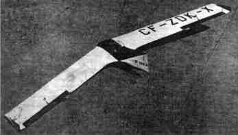
Figure 2
BKB-I ConfigurationFigs. I and 2 show the configuration for BKB-I. Its span of 40 feet (l2,2 m) and aspect ratio of 10 are somewhat lower than the suggested optimum of, say, 50 feet (15 m) and 12 respectively. Due to the small size, departures from the ideal of the flying wing have to be made at the start. The pilot is housed in a nacelle which is blended with the wing to keep interference drag low. The nacelle offers what is considered to be the only practical seating position for the pilot. From these two components, good lift-to-drag ratio and the desirable degree of stability and control must be obtained.
Longitudinal stability is obtained by combining the moment(nose up) of slightly stable airfoil with the moments due to twisted swept wing in conjunction with the location ot the centre of gravity forward of the aerodynamic center. The temptation to use the straight wing of the Fauvel or the "Flying Plank" type was discarded on two accounts. First is the lack of sufficiently stable airfoils of the low drag type and, secondly, the straight wing has no directional stability. In conjunction with the nacelle, which would have to protrude forward of the wing leading edge (to provide forwardc.g.) the combination would be decidedly unstable directionally. The sweep of 13 degrees chosen for this design is low enough to keep out of troubles associated with higher values and yet is sufficient to ease directional stability problems.
Aerodynamic Characteristics of the Wing
The controllable flight at low speeds and in tight turns demands great care in the selection of airfoil and wing plan form. The choice of low drag sections possessing some degree of the positive pitching moment is very limited. It is fortunate that the series of recently developed NACA sections tor the helicopter blades conveniently fit the requirements.
The chosen section is a 12% thick NACA S-H-12, cambered to give low drag bucket at high lift coefficients, and reflexed to yield small values of a positive pitching moment. An additional characteristic is the constant, moderately high maximum lift (for low drag sections) maintained throughout several degrees of incidence even at Reynolds numbers below 1 million. Curiously enough, the section seems less sensitive to surface roughness than the conventional airfoils.
With the span, aspect ratio, and sweep established, the remaining variables are taper ratio and twist. Weight economy calls for high taper. For aerodynamic reasons, however, especially in conjunction with the swept wing, it is imperative to use large chords in the tip region. An easily constructed rectangular wing was decided upon, especially since theweight penalty is negligible due to such a small span and aspect ratio.
It is known that twist incorporated in a straight wing, properly tapered for optimum drag. is generally harmful. It so happens that twist, necessary here, to augment the positive pitching moment, actually improved the properties of the chosen planform. This wing should be twisted to give, at a chosen incidence, elliptical load distribution and associated minimum induced drag for a given aspect ratio. Additional correction is necessary, of course, to maintain this type of distribution throughout the speed range. This correction comes automatically from the deflection of the elevators necessary for trimmed flight at speeds below or above that corresponding to incidence at which the glider is trimmed with the elevators neutral. There is another type of loading, resulting from wing aeroelastic deflection. This however is considered negligible in view of the high structural stiffness of this wing. Thus we have spanwise lift distribution only due to angle of attack, twist, and elevator deflection.
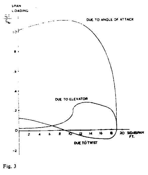
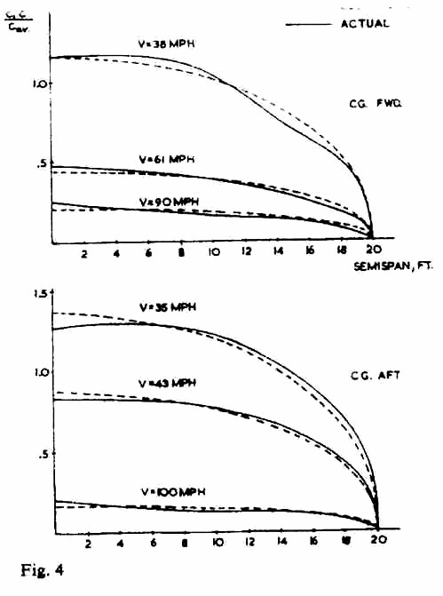
These individual unit lift distributions (fig. 3) are calculated using the Weissinger method. Thus, by combining the wing planform with twist, the elevator geometry and deflection, the optimum span loading can be maintained throughout the speed range (fig. 4).
The profile of the nacel1e was chosen to give least disturbance to wing flow. The maximum cross section of the nacelle is thus well aft of the wing maximum thickness, with top, forward part of the airfoil completely exposed.DragControl
Low drag waspursued throughout the design by reductions of wetted areas, use of geometry conducive to laminar flow, the above-mentioned induced drag control, and reductions of possible leaks, even at a cost of certain minor inconveniences
It can be seen that the spanwise distribution of lift, here identical with the distribution of lift coefficient since c/C av = 1,0 ( fig. 4), gives the desirable center section wing stall, since thelift coefficient decreases towards the tips.
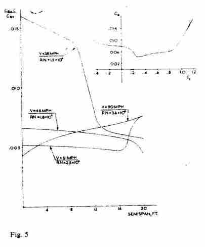
There is a penalty however in the related profile drag. At low speed, the center part of the wing reacheshigh local values of the lift coefficient with the associated higher profile drag (fig. 5). More judicious selection of airfoils along the span would improve the situation.
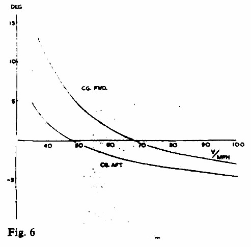
Longitudinal StabilityAs it was mentioned before, configuration yields a positive moment (nose up) which permits the centre of gravity to be located forward of the aerodynamic centre. The degree of longitudinal stability may be varied by c.g. shift. The fortunate feature of this sailplane is that the pilots position coincides with the centre of gravity of the empty glider located within the desirablelimits.The variations of pilots weight will thus have very small influence on the degree of stability. Elevator deflection to trim is shown on fig. 6.
Directional Stabilityand Control
The directional stability arising primarily from wing sweep is augmented by locating the centre of pressure of the side area aft of the centre of gravity. For this reason, the nacelle is well back and carries considerable dorsal area.
The directional control is obtained by individual deflections of the wing tip plates. These, when operated simultaneously, control the rate of sink, instead of conventionally located spoilers. This solution was dictated by the desire to keep the wing clean of leaks and irregularities, as well as economy of controls.
These wing-tip rudders are the primary control in execution of turns. Their use resultsin the almost correct amount of bank for the rate of turn. The ailerons, used for minor corrections, are rigged with variable differential which diminishes towards high speeds,a result of combined symmetrical and anti-symmetrical deflections.
Following is the brief account of the test pilot, Mr. Dave Marsden, from the flights performed so far:
Flight Test Reports
After a considerable amount of ground testing using car tows, and some minor modifications, the BKB-1 1ook to the air on its first aero towon the 10th of October, 1959. During the following weekends up until the 15thof November, 10 flights were made for a total of 4hours, l5 minutes, in the air.
The BKB-1 handled well in the air both on towand in free flight. First impressions were of sensitive, rapid response elevator control and surprising distances covered due to good penetration. Gentle turns were attempted at first then steeper ones. Good, coordinated turns could be made but strong rudder control was required to overcome adverse yaw. Ground tests had shown the directional control, by means of wing tip drag rudders, to be excellent.
The ailerons were made to continue the wing aerofoil section including the reflexed trailing edge. This acted as a fixed trim tab which gave a rather unpleasant nose down stick force which could not be trimmed out. Flight tests were continued without correcting this condition as time before the end of the season was limited and more flight data would be a useful basis for changes. Elevator control was sensitive with almost instantaneous response, a characteristic of the tailless configuration due to low pitching moment of inertia and low aerodynamic damping in pitch.
Roll response was lively with an estimated 4seconds to roll through 90 degrees at 50 miles per hour airspeed.
Directional stability was about normal, disturbances set up by kicking rudder or suddenly releasing full rudder were highly damped.
Drag rudders used as spoilers were not as effective as might have been desired. A very steep approach could be made by sideslipping, a manoeuver which is safe to use on the approach to landing because of the way the BKB-1 returns smoothly to un-yawed flight.
The aircraft proved to be easy to land. Good landings were made over a wide range of touchdown speeds with no tendency to porpoise or nose over.
The stalling characteristics were not fully explored on these preliminary flight tests. When the stall was approached by gently reducing airspeed, only a controlled mush resulted. Tufts showed separations beginning at the wing root near the trailing edge and spreading spanwise.
The BKB group have been successful in building a sailplane which is easy to handle and rig, and, except for the difficulty with trim to be remedied, has satisfactory handling characteristics. Performance tests have not yet been made, but the aircraft has noticeably better penetration than the medium performance sailplanes in the Olympia II, Schweitzer 1-26 class.
Description of the Prototype
From the preceding brief description of aerodynamic features, it can be seen that the design achieves great simplification of form not completely matched as far as the internal construction of the prototype is concerned. By virtue of the constant cross-section, the wing lends itself to a number of simple manufacturing procedures. Unproven configuration, however, did not warrant additional effort in that direction. With some exceptions, a conventional type of construction is employed.
The wing consists of a multi-laminated box spar, a leading edge molded of plywood, and conventional girder type ribs, centrally reinforced by plywood webs. In order to maintain the contour, ribs are spaced every 4 inches in the nose and at twice that spacing aft of spar which is located at 30% of the chord.
Covering consists of sheets of plywood spliced to the leading edge, and joined together at the trailing edge. There is a very thin spanwise member well forward of the trailing edge to support the covering. This method gives a very rigid leadingedge, does away with difficult bending of large sheets of plywood around the nose, and reduces the chordwise step at the sparwhere the fabric normally starts. The trailing edges are alsovery rigid and true to theoretical shape. Ailerons are built and covered with plywood on the wing jig simultaneously with the wing. Upon completion, the slot is cut along the hinge in the upper and lower skins. Resulting is a very stiff, somewhat heavy wing. A high degree of stiffness was considered a necessary feature in view of its effect on the behaviour of the sweptwing.
The spars are picked up at the root by steel fittings made of 0,072 4130 steel plates bolted together through each spar cap and joined by a vertical tapered pin at the plane of symmetry. The fittings carry the normal bending loads and the horizontal bending loads in conjunction with the aft nacelle bulkhead picking up the loads from the wing drag brace.
The nacelle structure consists essentially of two heavy bulkheads forward and aft of the pilot. These bulkheads, designed to take landing loads, are connected by the keel at the bottom, two longerons at the sides and cockpit frame at the top. Covering is of plywood reinforced by light formers. The nacelle is suspended between heavy wing root ribs at four points located in the planes of the bulkheads. The rear bulkhead is attached at each side by means of a universal joint to the apex of a triangle formed at wing root by a heavy rib and a diagonal rib acting as a drag brace.
The assembly of the glider consists of engagingconnections at the rear bulkhead by sliding the wing forward onto a pin fixed to the bulkhead, engaging the spar fitting by slight forwardmovement of the wingtips. This movement engages also the shear connections between the wing and front fuselage bulkhead. Insertion of the tapered pin into the spar fittings completes the assembly.
Control runs (mostly consisting of cables) are so designed that the previously described assembly of the main components of the glider brings into contact all the necessary connections of the complete control system.
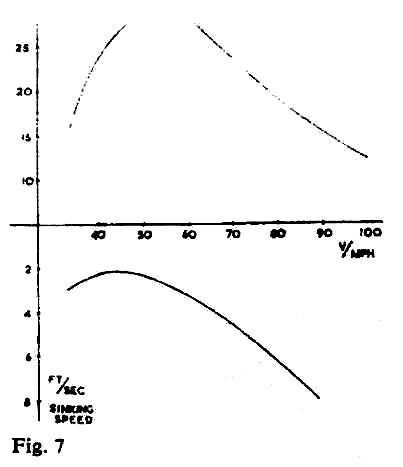
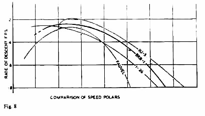
Fittings are of the simplest type, designed to be made out of steel plates and light alloy extrusions with the help of band saw and drill press. In order to preserve the feel of controls and eliminate dead motion, ball bearings are used for all movable connections. The prototype is equipped with small dual wheels. They are mounted on the skid and protrude 1 inch below it. Estimated performance data are given in fig. 7 and compared with some other sailplanes in fig. 8.
Comments by Dipl.-Ing. Justyn SandauerDipl.-Ing. Sandauer stated that since Irena Kaniewskas paper was unfortunately not available, he wished to publish a resume of her ideas on the influence of wing elasticity on 1ongitudinal stability of a tailless sailplane.
Designers of the ideal "flying wing" sailplane meet difficulties in designing a tailless sailplane of high performance with the proper flying qualities.
Tailless sailplanes with unswept wings require large vertical surfaces to obtain sufficient directional stability which tend to nullify the reduction of the drag of the fuselage and the horizontal control surfaces. Tailless sailplanes having swept wings obtain sufficient directional stability but they show anomalies in the longitudinal stability.
Aerodynamic analysis of a swept wing, tailless sailplane assumed to be a rigid structure, can be shown under the properly chosen conditions to have quite satisfactory static and dynamic longitudinal stability. But experience shows that swept wing tailless sailplanes, when encountering gusts, even quite weak ones, show an exaggerated sensitivity. In the case of very turbulent air, this can even result in structural failure in flight.
In general, one has attributed this "super-sensitivity" in gusts to the very small moments of inertia and the small aerodynamic damping in pitch, as a basic characteristic of tailless sailplanes. But as opposed to this conclusion, it is found that tailless sailplanes without sweep do not show this sensitivity in gusts any more than orthodox sailplanes.
This phenomenon of "super-sensitivity" of swept wing tailless sailplanes can be explained if it is assumed that the sailplane is not a rigid structure but has flexible wings (and certainly high aspect ratio wings are extremely flexible) and that the bending of the wings influences the flight path.
Alteration of the bending of the wings under the influence of change of load factor "n" of the sailplane, caused by gusts or by operating the elevons, leads as a result to an alteration to the angle of incidence of the outboard portion of the wing. This is a sort of automatic piloting of the sailplane by itself which increases the load factor "n" to such an extent that the maximum lift coefficient may be reached when, if the speed is sufficiently high, the wing fails in flight.
This is a phenomenon rather like longitudinal instability under the influence of the change of load on the sailplane. A well-trained pilot can keep the sailplane from such a flight condition by adjusting the angles of the elevons and thus counteracting the influence of the wing tips caused by their bending. Such pilotage is very difficult. It resembles flying an aircraft which is unstable statically.
A more dangerous phenomenon can occur in the case where bending oscillation of the wing appears under the influence of an external impulse, as for example a gust.
The period of this oscillation is approximately independent of the flight speed and for a high performance sailplane with high aspect ratio it amounts to 0,3 + 0,5 sec., while the period of the short-period longitudinal oscillation of the sailplane varies with the flight speed. This latter period depends, of course, on the geometrical shape of the sailplane and it is several seconds for orthodox and a half to one second for tailless sailplanes at low flight speeds.
At higher speeds the period of longitudinal oscillation decreases and, in the case of tailless sailplanes, it may easily approach the period of bending oscillation of the wing. In this case, resonance occurs which may cause oscillation instability, and, as a consequence, the failure of the wing.
It is necessary to add that the pilot is not able to damp this oscillation by operating the elevons, their period being too short for human reaction time. In conclusion, one can say that the maximum speed of the swept wing tailless sailplane designed for high performance should not be greater than:
unless one has devised special means to counteract the influence of the wing in bending.Comments by Dipl.-Ing. Hans Zacher
I have flown many tailless aircraft with swept and unswept wings, with and without engines, including the prone pilot position. I have flown these with pleasure and found that they mostly had quite safe flying qualities, although not particularly good ones, and I was able to determine that they had low sinking speeds at low wing loadings.
However, I still do not believe in a good future for tailless aircraft. They have certain basic characteristics, some of which may possibly be improved upon, but in general cannot be obviated. The most important of these are briefly as follows:
(1.) In order to maintain a regular spanwise lift distribution and to avoid a reduction in performance, the elevators attached to the wing should be as far as possible remain in their neutral position. To attain this means that a very closely specified centre of gravity must be maintained, which is very diffcult in operation with pilots of varying weights.
(2.) When the elevator is deflected upwards, it should cause an increase in incidence for the wing as a whole and therefore an increase in lift, but the elevators have at the same time a flap effect which reduces the lift. Since the flap effect acts more quickly than the change of incidence, one experiences sometimes an unsteady flight path and also rather sharp shocks in landing.
(3.) The weak longitudinal damping and the small moment of inertia about the transverse axis increase the above-mentioned difficulties (mostly at certain particular speeds) and assist the development of short period pitching oscillations.
(4.) These oscillations in the case of swept wings can, for example in gusts, be accentuated by bending oscillations of the wing, since wing bending causes an incidence change of the outer part of the wing and therefore a change in pitching moments.
(5.) The weak directional stability and inadequate yawing moments due to yawing leads to difficult lateral stability problems. In ordcr to solve these, as well as the directional control, many experiments have been done (brake flaps or wing tip discs, etc.) but as far as I can see very large vertical surfaces should do this job satisfactorily.
(6.) From the structural point of view, there are simple solutions. But one must take into account such things as twisted spars, skew ribs, sloping control hinge lines, etc. when swept wings are used.
In conclusion, one must certainly assume that with tailless aircraft the compromise between low production cost, good performance and pleasant flying qualities is more difficult to find than in normal aircraft. I would even suggest that a comparison would always turn out in favour of the normal type of aircraft.
Comments by B. S. Shenstone
The remarks by Dipl.-lng. Sandauer on the twist which occurs when swept wings are bent are generally correct and are a matter of experience. However, I wish to mention that although this phenomenon usually occurs, it does not necessarily occur. I refer to the possibility of so designing the wing structure that under flexure there is no change in incidence from root to tip. This may be achieved by locating the flexural axis well aft in the wing and suitably proportioning the torsion-resisting portions. Such a wing, called "Aero-isoclinic" by the late G.T.R.Hill, was incorporated in the Short "Sherpa" swept-wing tailless experimental jet, and was found quite satisfactory. Apart from the unusual structure involving a webless spar at 25% chord and shear webs at 35% and 60% chord, the wing leading edge structure was split in such a manner as to reduce its torsional resistance. The success of the "Sherpa" wing does indicate that the possibility exists of designing a swept tailless sailplane with the desirable control characteristics of the unswept tailless type.