|
As Presented By Henry
Jex
|
| I n the early
1980s Dr. Paul MacCready of Aerovironment, Inc., became interested in
the flight properties of large pterodactyls (literally wing-finger).
His interest was piqued when he saw a complete fossil pterodactyl.
But the real incentive to build a flying replica was the 1971 discovery,
by Professor Wann Langston and his graduate student Doug Lawson, near Big
Bend, Texas, of the largest pterosaur ever found. It has a wingspan
of 36-39 ft., about the size of a 4-place light plane. Lawson named
it Quetzalcoatlus northropi (QN®); the former for the Mexican sun god
and the latter in honor of Jack Northrop, designer of the large flying
wing aircraft of the 1940s.
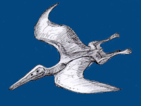
(Courtesy of: http://www.geocities.com/CapeCanaveral/Lab/1638/pterosaur.html) At the same time the
Smithsonian Institution was starting another IMAX-Format film, called On
The Wing. It was to compare the flight achievements of various creatures
with those of mankind. It was decided to attempt a free-flying replica
or QN for the film to: represent the ultimate in pterosaur achievement
and; help resolve some contentious issues in paleoaerodynamics, e.g., that
a creature of this size might not be able to fly.
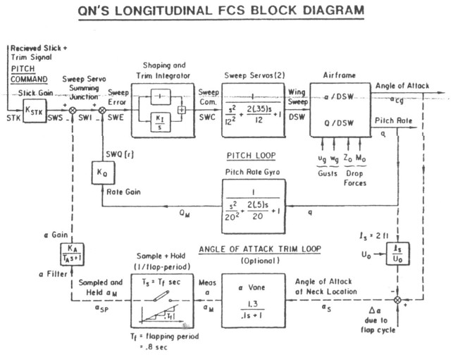
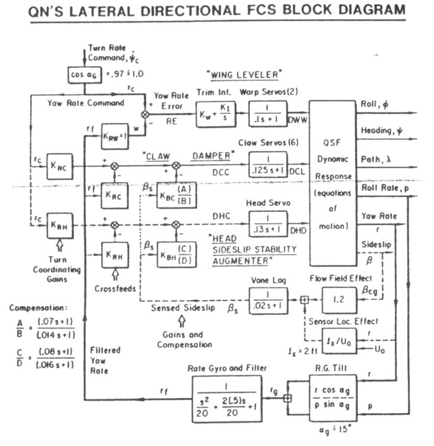
Using claw-dampers, in lieu of yaw-dampers;AeroVironment showed that proper twisting of the wing as it flapped, plus a much more sophisticated airfoil, used together, could provide the necessary propulsive efficiency to achieve level flight with less than 1hp (746W). With these obstacles overcome, it was decided to build a half-scale replica having a span of 18ft and target weight of 30 lbs to make construction and handling easier while still resolving the scientific issues. One result of the workshop is shown in paleontology artist Greg Pauls rendition of the flight worthy QN. Its modern soaring-bird like appearance should not surprise us; after all, the QNs Program Manager had over 100 million years to refine its design! A very important result of the blending of various disciplines at the workshop was a new interpretation of the wing airfoil and structure. Based on fossil evidence of smaller pterodactyls, from French caves, it seems that their airfoil was not just a bat-like membrane, as often depicted. Our new interpretation is that the finger bone was the leading edge of a double-surfaced membrane, with chordwise flexible cartilaginous ribs, the precursors of feather shafts. The leading-edge muscles were ahead of a lazy-T shaped spar, and when they contracted for downward or upward motion, they gave appropriate leading-edge camber, downward or upward, respectively. It also became apparent that the slab-sided head, with sharp edges and a aft crest, was not just cosmetic. Its resemblance to the strake-wing of an SR-71 Blackbird supersonic aircraft was compelling evidence that it was used as a forward steering rudder capable of sustaining large angles of sideslip without stalling. This is just what is needed for a canard rudder. Henry showed analytically that if the QN actively pointed its head where it wanted to go, then the heads deflection with respect to the neutrally-stable wing/body/feet combination, would stabilize the ensemble. However, it would have to remain unstalled over a large local sideslip range. Professor Langston returned to Texas and found that the QNs head-neck joint was a ball-joint with large deflections possible a good example of theory guiding and interpreting 100 million-year-old data! Another feature of the QN fossils is their prominent claws. After watching seagulls soar, we noticed that they used their upper tip feathers as one-sided drag spoilers, to produce effective yawing moments. Hence, we proposed to use the QNs claws actively opening upward to give damping in yaw, i.e., as claw dampers. The use of fore-aft motion of the wing to trim hang gliders is well known, but birds also stabilize their neutral pitch stability by more active sweep control, so this was used on the QN. The more we studied QN the more sophisticated and clever its detailed features became. The project adopted a policy that the QN replica should, whenever possible, use means similar to the original pterodactyls to help answer numerous scientific questions about feasibility of their flight performance and control. It is interesting to compare the means for achieving automatic flight control for: a) stability inner-loop regulation against disturbance due to gusts, wing-flapping sweeping and, -twisting, wing asymmetric lift and thrust due to imperfections in construction, and; b) path-control outer-loop following of guidance commands for airspeed (trim, average angle-of-attack), rate-of-climb/descent, and (gently) banked turns. Following the feasibility workshop in 1984, the foregoing stability and control concepts were evolved and analyzed, and the schemes noted above were given priority. Several areas of high risk, due to lack of prior data or validated theory, had to be researched and developed before the detailed design could be defined. These risk areas were tackled independently, focusing methodically on one at a time to minimize the compounding of R&D problems in any one experiment. In the flight dynamics arena there were: control of pitch trim by active wing sweep; pitch stabilization against the wings flapping moments; lateral control by head deflection, and; claw damping and launching techniques. Inside the QN there were uncertainties of the power train design, wherein light-weight versus low friction was in conflict. The use of samarium cobalt electric position servos for primary power was novel, as was the combined wing flapping and sweeping mechanism. The wing construction, to enable it to be stiff in bending but limber in twist, was a structural challenge. The first problem to be solved was the stabilization and trim in pitch by means of active control wing sweep. Testing these nonlinear radio-controlled model aircraft servos with the wing attached was a story in itself. They used frequency sweep inputs and a video camera record of the command and response motions, to yield surprisingly good Bode plots. The first test glider was an R/C model sailplane of conventional design with a span of 8 ft and a weight of 6 lbs. It had an angle-of-attack (AOA) vane at the top of the vertical tail, which sensed the tails local AOA, including wing downwash. This was fed back to the wing sweep servo to sweep the wings forward (nose up) if the AOA decreased, and vice-versa. As the gain of this feedback loop was optimized, the horizontal tail tips were progressively cut away, so that there finally remained only a 4 inch stub, such that the wing-body was statically unstable. It was an eerie sight to see this tailless glider soaring in the hill-induced upwinds, with its wings hesitantly hunting fore-and-aft as random gusts disturbed its equilibrium. The experiment proved the principle of obtaining pitch stability by active sweep control, they think was the first time in an aircraft. It remained to change the sensed feedback from tail AOA to body pitch angle and rate to resist the large pitching disturbances due to wing flapping. A model helicopter rate gyro was adapted for this purpose, and its pseudo integral (long lag) was used for short term attitude holding. The control law was, therefore, proportional-plue-integral correction of pitch rate errors. Their attempt to use a sample/hold of AOA as a feedback, sampled once per flap at the peak up-flap. This was found to be too slow to quickly trim the pitch loop. Instead, a Morganberger Observer technique was employed. Like the well-known Luenberger Observer in modern control theory, in which other sensed states are combined to provide a surrogate for a non-sensed state, the Morganberger Observer estimated the longer-term airspeed and AOA by a flight-trained neural-net state estimator. It was later found necessary to increase the flapping rate (propulsive power) in the final QN to make up for its increased weight and the drag of its fur covering. The final flapping rate was about 1.2 1.5 Hz. This was near the wing-sweep servos resonant frequency, so the pitch control system was operating very near its theoretical limit. The next challenge was the proposed lateral control scheme using the head-to-steer and claws-to-damp the yawing motions of the QN. The 18 ft span lateral test glider was a stable flying plank and built to the approximate configuration of the half-scale QN. It used inboard tailing-edge flaps for airfoil reflex and pitch trim, tip ailerons to simulate wing ways effects, steerable heads of various test configurations and, an early version of the yawing-moment claws. The head was on a universal joint so it could be moved laterally by powerful Condor servos. It was launched by winch using a wheeled dolly and airborne detachable tail assembly. A parachute was later added to the wing so it could landed more gently if it got out of control. The first lateral control loop to be developed was an adaptation of a light plane wing-leveler used to prevent spiral instability. Its sole sensor is a turn/roll rate gyro, tilted 15 degrees so as to pick up the positive components of roll-rate and yaw rate (the latter is proportional to bank angle when the Dutch Roll mode has died out). This worked perfectly with the tail on, but demanded a high degree of artificial sideslip stability with the tail off. The sideslip stability augmenter uses the sideslip sensed as near as possible to the CG, to turn the head in an opposing direction. After lengthy experiments for the sideslip sensing vane location, the best proved to be just under the QNs neck on the centerline. The yaw damping was supplied mainly by the claw-dampers described earlier. The turn rate signal was fed directly to the claw servos to oppose yaw rates. One of Henrys most esoteric aerodynamic assignments was to estimate the increasing drag and decreasing lift from progressively extending the claws. It proved easier to put a small servo on each of the three fingers than to design a complex mechanical linkage to do the same job correctly the first time. As evident from the foregoing chronology and control concepts, the lateral-directional automatic flight control system is much more complex than the pitch system. A crossfeed from sideslip-to-claws is used to give some insurance against head servo lockup. Thus the claws help the head in its essential role of providing artificial weathervane stability like the real pterodactyls. The remote pilot only commands the turn rate. The system was modeled to assure robust operation in following commands and fighting the numerous severe disturbances. These include: wind gusts; large yawing and pitching moments due to wing flapping asymmetrics, and; crudely characterized plant dynamics and nonlinear sensor and servo dynamics. The spar was C-shaped to be stiff in bending but limber in twist, and the warp servo was connected near the root by a torsion shaft to the region near the claws. The carbon-fiber rib caps were bonded onto a solid foam core having the proper reflexed airfoil shape; the form between each of the 215 ribs was cut away with a hot-wire coping saw. They added a wing covering of thin rubber dental dam material, which did not impede the required wing twisting. This gave an aerodynamically efficient wing approaching the sophistication of a pterodactyl. One of the valuable lessons from the prior Gossamar project experience was to use weak-link joints between the appendages most vulnerable to breakage; the head; neck; feet, and; yaw vanes. This facilitated quick repairs. Some of the video footage Henry showed included several shots of hard landings that had to take advantage of quick repair capabilities. The avionics were mostly analog circuits, built on printed circuit cards having a generic format: inputs, filters and compensation, and outputs.
|
|
|