Having
come across No. 149 TWITT Newsletter 1998, I wish to become a member and
request lots of information. I am a senior citizen, hold a degree
in horticulture and am a qualified lepidopterist, breeding butterflies
and operating the Darwin Butterfly Sanctuary. I am a member of the
Australian Society of WW I Aero Historians and am trying to procure the
original plans to build a Sopwith Pup before I die. If any of your
members have any information I would appreciate it. I am a member
of the Top End Ultralight Club and do training in a Drifter, a Thruster
and other aircraft, as I need an ultralight license even to fly the minimum
aircraft Scout in Australia; not like in America where no license is
required if certain rules are adhered to.
Now to the main reason
for joining TWITT. As by the address you can see I Iive at the top
of Australia, but when Cyclone Tracy blew me out of Darwin in 1974, I bought
a farm in Victoria to house my family. The commute between Darwin
and Victoria is 4200 km each way over roads that are not always the best.
There has to be a better way to make this trip.
In conjunction with
a Frenchmen, we have been trying to design a FACET similar to Barnaby
Wainfans who I believe is one of your members (ed. - he is not, but
we stay in touch). An Australian designed a FACET OPAL in which
he died and I have repeated dreams about it. 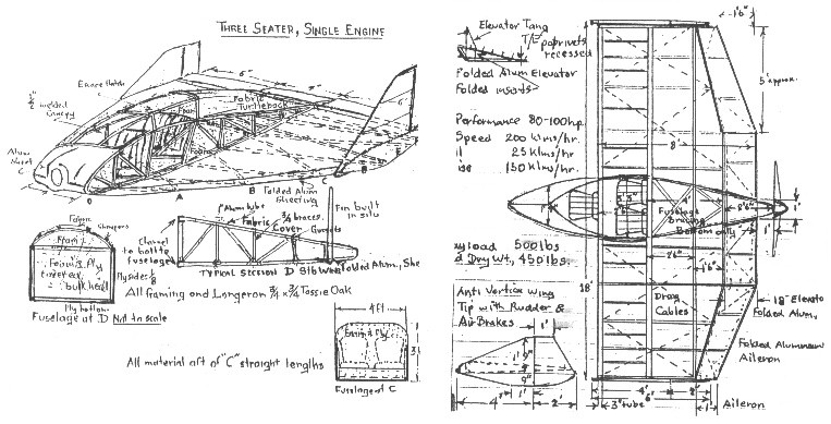 My main concern is designing and building a Long Distance FACET or flying
wing to commute between the top and bottom of Australia so I can manage
both of my properties.
My main concern is designing and building a Long Distance FACET or flying
wing to commute between the top and bottom of Australia so I can manage
both of my properties. 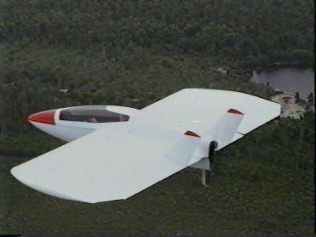 I believe commuting by plane is safer than the long distance by road and
it will be much easier on my wife and little girl than the long ride.
So with my family on board it needs to be safe and I have heard it is hard
to stall a FACET or flying wing and they just mush down; is this correct?
I believe commuting by plane is safer than the long distance by road and
it will be much easier on my wife and little girl than the long ride.
So with my family on board it needs to be safe and I have heard it is hard
to stall a FACET or flying wing and they just mush down; is this correct?
I have in mind twin
engines for safety; small four strokes in-line or opposed or twin small
radials. I am no aero engineer, only an old plumber, so need a presentation
of different models for selection. I have been playing around with
an old 1930s concept where the designer quoted a 4-wheel pusher would
probably be the future plane. I have a 5-wheel sketch as below.
In my dreams Scott Winton keeps telling me that the wing should be the
cockpit. Scott designed the Facet Opal which he used to break 4
records, including climbing to over 30,000 on 40 hp, before a fatal accident
with the aircraft. If you have any photos of the Facet Opal I would
appreciate one.
I have been making balsa
models and have duplicated the ply sandwich idea with a trangle shape front
to a square where the passengers sit in a triangle at the rear with twin
pushers and a tri landing gear, conventional 3-axis control. The
passengers are recessed into the main spar of
the wing putting them at the CG, which still allows the plane to fly solo
with the pilot up front to balance the weight of the engines aft.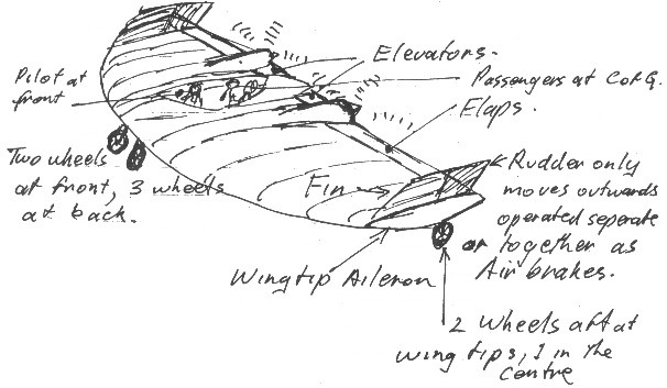
The engines would have
to be close together for one engine to still keep the aircraft in flight
if one failed. Do you have a concept in your files as a facet or
flying wing? Ply/foam fuselage with 18 deep wing at the center to
6 outboard, approximately 20 wing span, 12 chord at the fuselage and
as a guess twin 60 hp motors.
As I have built many
ply boats I think the ply/foam combination would be the easy way to build
as all you need to do is order custom length ply, mark out the shape and
cut with a jigsaw. You can then trace it onto another sheet giving
you a right and left hand side, then joining them with bulkheads for seats,
etc.
Using two light weight
engines in the wings of about 60-80 hp which could easily be unbolted,
the whole plane could be dismantled and housed in the family garage.
If the motors weighed about 80 lbs. each - say a F30 Hirth 95 hp at 38
kgs - two motors would be about 170 lbs., the same weight as a pilot and
then most of the balance problem would already be solved if the passengers
sat at the CG. Little ballast would be required for balance and if
the pilots seat is moveable fore and aft to correct most balance problems.
An 8 aluminum tube sub spar at the CG could be welded up as the fuel tank
with an equalizing transfer pump to port or starboard to balance it laterally.
Fuel used at the CG point would not affect stability.
I believe that I could
build a Facet or wing using the ply/foam system obtaining a craft that
would float if forced down on water. It could be very cheap as I
would recycle auto main leaf springs for the main wheels traversed across
the fuselage with one forward trailing castor wheel and individual brakes
on the main wheels. These would be operated by a lever moved either
side for differential braking or pulled up vertical to operate both brakes.
A simple drum bolted to the wheel with external brake bands operated by
cables.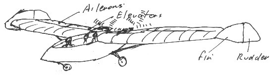
I would use foam
ribs with 1 wide ply cappings and cover the leading edge to a D shape
with 8mm ply and folded aluminum sheet for rudders, elevators and ailerons.
A complete main wheel
bolt on external brake system is marketed in Australia for $80.00, 12
castor wheels $95.00 each, and 16 wheels complete $82.00. Springs
at no cost; recycled from wrecks. As I have also been in charge of
large sheet metal works, folding the control surfaces from single sheet
aluminum would be a breeze. The fixed fins at the end of the wings
with rudders only operating outwards individually for yaw and both together
as air brakes would be great. The castor front wheel with individual
main wheel braking would give good steerage and if flaps are incorporated
with a over-center locking lever, you could have a S.T.O.L. effect.
Having done a rough
calculation on materials in Australia, I could build a 14 fuselage for
about $1,000 complete and the full de-mountable 20 wings for $1,000 also,
using recycled gear. What the engines would cost I do not know, but
a rough estimate using Subaru as an example would be another $3,000 for
the two. This looks like $5,000 for a three seater, 300 hp aircraft,
with a 200 kph cruise speed, 60 kph stall and 65 kph liftoff in about 25
metres. This is all guess work so can your members tell me how close
I am. I know that Subarus can produce about 150 hp each and with
pusher propellers 4 blades should be very efficient if the airflow is undisturbed
and directed without turbulence to them. Deep airfoils would give
a lot of lift, say 18 at the root and 6 at the tips, keeping the trailing
edge straight for each manufacture. This plane should be able to
fly on only one motor.
Further
to my previous letter, $30 US is included for membership, info. and postage.
As I noted in my previous letter, I need to build a 3-seat powered Facet
or Flying Wing to fly from the top end of Australia to the bottom, as
it is 4000 km between my properties and a lot of it over tiger country.
I would intend on landing in some of it for camping, fishing and shooting,
so I can live off the land enroute.
I have one son who is
out in the remote coastal mangrove areas catching mud crabs as his living.
Generally he brings in a load of crabs about once a week, but sometimes
he doesnt come in for a week or more and I become very worried about him
because of the dangerous waters, rip tides and threat of crocodiles as
he is always alone.
This brings me to my
added request in relation to my Facet or Flying Wing, which I want to build
for commuting between my properties. Is there any amphibious flying
wings in America as I could use the same plane to scout his areas
of work, deliver supplies and transport some of the crabs back to Darwin.
Fishing in the same area for fresh fish would also be a benefit for my
family, which loves seafood.
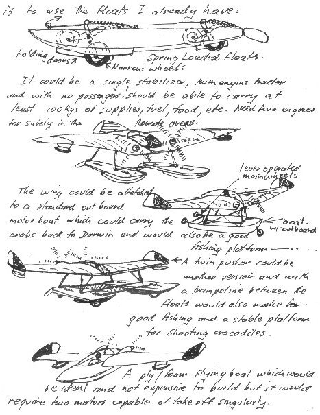
It could be a single stabilizer, twin engine tracker and with no passengers should be able to carry at least 100 kgs of supplies, fuel, food, etc. I need two engines for safety in the remote areas. The wing could be attached to a standard outboard motor boat hull, which could carry the crabs back to Darwin and would also be a good fishing platform.
A twin pusher could be another version and with a trampoline between the floats would also make for good fishing and a stable platform for shooting crocodiles. A ply/foam flying boat which would be ideal and not expensive to build, but it would require two motors capable of take off singularly.
Has anybody in America done something like this; I know there is a trike with an inflatable boat on the market in your country.
I enclose a further $30 US for postage, information, etc. The photo I enclose shows the internal wheels in the floats with the doors which close and seal when the wheels are raised by a control wire and the springs which are internal return the wheels to the up position and retract the doors. The floats are very wide and should support at least 750 kgs each; both wheels fold backwards in a over-center position in the landing mode for airstrips land and grass.
Porpoising the floats should allow the plane to unstick from the water on take off when loaded and you could taxi around to make a wake to get air under the floats. I also have a trailer which the floats can roll straight onto with the wheels extended.
I also enclose a photo of the Mk III Scout which I am resurrecting; one of the first ultralights - 1970, which I am donating to the Darwin Aviation Museum after I modify it to a tri-retractable landing gear with floats and make it a bi-plane, combing the modifications other Aussies have done!!!
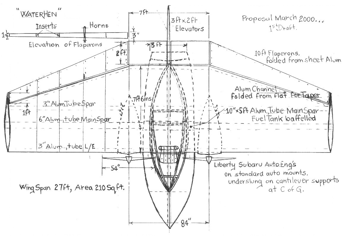
Further to my previous concepts which you have
published, I now submit the concept I want to proceed with. It was
triggered by the Choucas by Noin Aeronautiques (two seater, Vmax 170,
Vc 130, Vmin 60 kph, 503 Rotax & 260 kgs empty weight). The wing
and rudder assembly I believe seemed suited to adapt to water operation
with the large parallel center wing section with tapered tips, although
it was a mid-wing. The side-by-side seating made it a wide fuselage
which lent itself to development of the hull form and raising the wings
to a high position to clear the water as a seaplane. The large rudder
also appealed to me for good control when water taxiing in conjunction
with throttle control of twin engines.
Although the Choucas could
be flown without power because it had a large wing span, the caption was
that flying wings were hard to pilot. I have doubted the wing width,
but reduced the wing span to about half. I want a slow landing speed
so have made the wings deeper for more lift.
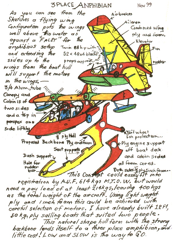
I have selected twin engines for safety and opted for a full width bench seat at the CG for passengers and camping gear. An aircushion seat pressstudded (ed. I imagine he is referring to Velcro) to the bench for comfort, easily removed to pack gear using the same seat belts to secure loads.
Using the ply foam construction and fiber glassing the complete external surfaces, I could produce a very strong hull. Using the throttles of the engines at different revs, and a large rudder, water steering would be simple.
The proposed hull width is 46 and approximately 12 long. I believe a plank wing would be suitable. Using aluminum tubing main spars could also be used as fuel tanks which would be at the CG and, would not give any balance problems as fuel is used up.
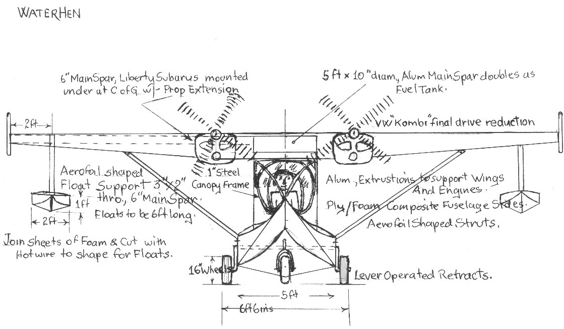
I want to build this to a very basic design using the most simple ideas. These include using lever operated, torsion sprung (VW rear suspension of the Kombi Vans) retract for the wheels. Differential, lever operated cable braking system with external brake drums. It must have adequate wild terrain clearances as the prime purpose of the design is a long distance commuter over Tiger country. I will use strut braced wings of foam ply with aluminum 6 tube main spar or even larger, and; a deep airfoil section in the center, tapering to the ends in depth only. I have no idea of the span or chord and hope members may assist me in the wing design.
Would you copy some of the sketches and dissect enough information out of this letter to distribute to the members. I want as much criticism and help to finalize plans for presentation to the Australian Ultralight Federation and the Sports Aircraft Association of Australia.
Many locals are interested in my Ornithopter which I mentioned in my previous correspondence, but expressed disapproval of the gull wings. I have read the articles of the Raven Wing in the TWITT newsletters and I believe my gull wings will work and, using the wing warps should have adequate control. Because I am 70 years of age, I have added a trike base for power assisted self launching with a comfortable air seat and go-kart steering. Using the soft cover book on sailplanes which I procured through the TWITT newsletter, I believe 25 hp should be adequate to get me airborne and only need about 5 hp to maintain flight seeking thermals.
I still fly every Sunday morning at the Top End Ultralight Club where many self-built aircraft have arrived lately, but as yet no flying wings. But trikes, especially the Australian Edge with the Streak wing capable of over 100 mph are arriving weekly and all these are basic flying wings.
The main thing is I want to achieve all my aims before my used by date expires and enjoy flying in craft I have built myself. I cannot think of anything more satisfying in life.
Thank you for printing my concepts in the newletter as by distributing your newsletter at the Top End Ultralight Club, my concepts have created that much interest that two people also want to build the same plane. May the wind be always in your hair.
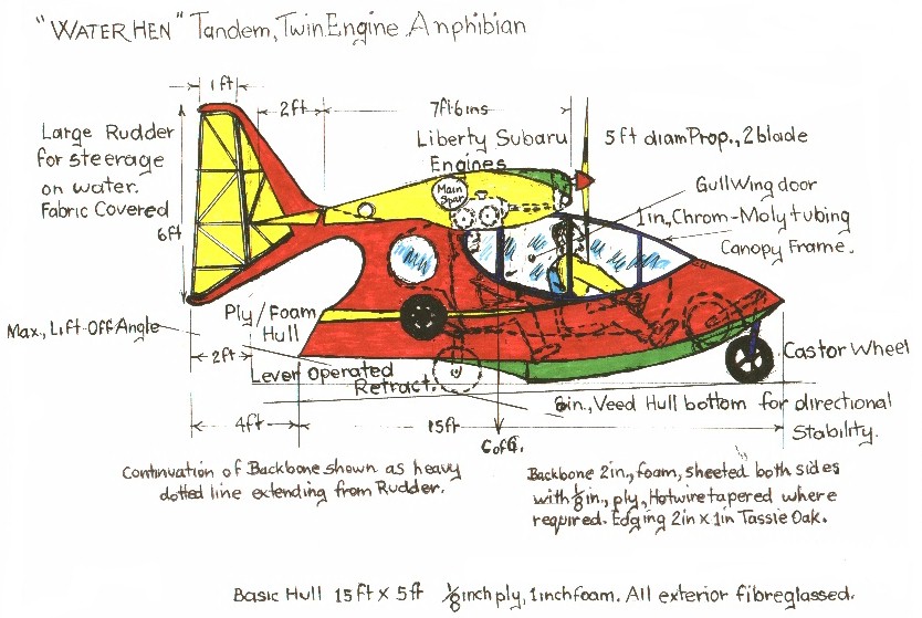 |
Hull Length
15
Total Length (nose of tail) 19 Hull Width 5 Tail Height at Trailing Edge 6 Wing Span No Value Center Chord 76 Engine Center Lines 84 Prop Diameter 54 Elevators Chord 2 Width 7 Flaperons 10 |
 |
|
February 4, 2001
TWITT:
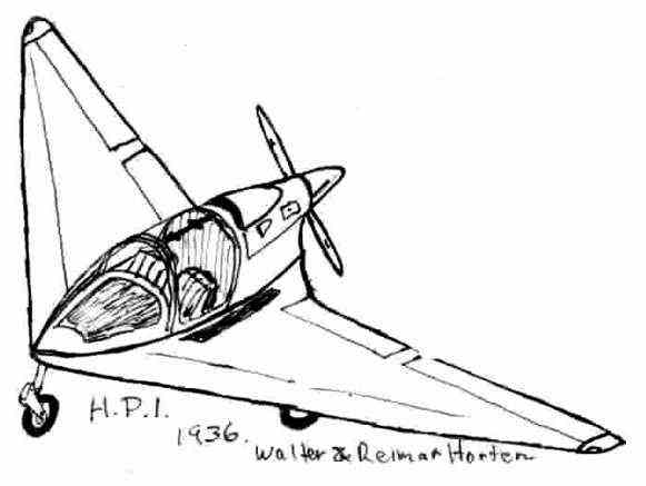
Having found a February
1996 Pacific Ultralights magazine with a tribute to the Horten brothers,
written by Rob Germon of New Zealand, it featured the fabulous H.P. 1.
The H.P. 1 was a side-by-side two-seater with a baggage load of 90 lbs.,
a range of 615 nm., and a top cruise speed of 165 kts., on 90 hp.
It had flaps with a stall speed of 38 kts, rate of climb of 1050 fpm at
gross load.
I believe that the H.P. 1 could be developed from its original all aluminum construction to a modern composite ultralight aircraft much cheaper than the normal 3-axis trainers like the Drifter and Thursters in a much more economical operating costs in the ultralight field. Just looking at its drag free shape even with fixed undercarriage it must be better than all other ultralights. Are there any plans available? Sincerely, Terry (The Tiger) Baxter (ed. From the drawing you included this looks
very much like the PUL-10 that is currently being developed in Germany.
We have presented material on this in past newsletters and as far as we
know there are no homebuilder plans available at this time. I think
the plan was for kits to be made once all the bugs were worked out, but
the program is behind schedule.
February 4, 2001
TWITT:
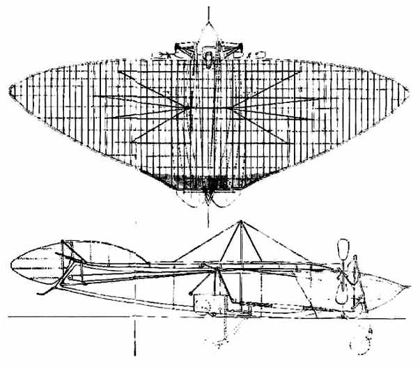
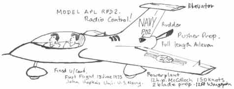
Having in my possession a drawing of French inventor
Pernauds first model aeroplane which he built and flew in 1871, I was
further intrigued by his twin-propellered monoplane, patented in 1876.
This remarkable machine of single control column, retractable undercarriage
and amphibious into the bargain must have been the forerunner offer of
the later Facets. It also shows the elevator, fin and rudder.
It is my intention to
build a rubber powered model of this design using the complete transverse
spars as shown with thin bamboo strips crossing the spars as ribs and papering
the whole wing with the elevators attached to the trailing edge as shown
in the drawing with the fin in situation to the wing also. Notice
the aerofoil shape of both the rudder and elevators. I do not believe
the landing wires are necessary in the model. Although this concept
only had yaw and pitch control, the low CG due to the hull shape and wheel
weight it should have been stable in perfect conditions for flying related
to the power source which I would surmise would be a belt driven by a light
weight steam engine of those days. Even the spring tail skid for
rudder protection for land takeoff was a good thought as the aerofoil shape
would have kept the craft in ground effect for some time.
Terry (The Tiger) Baxter
(ed. Some very interesting drawings.
We would be interested to see pictures of your completed model, hopefully
in successful flight. Keep us informed of your progress.
March 8, 2001
TWITT:
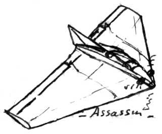
As a matter of interest I came across a very basic self launching slope soarer called ether Assassin in a May 1999 Airbourne magazine of delta concepts. It was stated that a 48 model was extremely aerobatic and would fly in 40 kt wind without ballast. If this is the case, why has not a similar man-carrying ultralight been built, or maybe one has, but living in such a remote area I had not come across one in the magazines and EAA does not seem to feature the flying wing concept. It appears to have separate elevators, ailerons and rudder, but I believe elevons would be enough with the rudder input for adverse yaw and the elevators could become flaps of the center blended wing area.
From my readings, it
appears less power is needed by the flying wing concept due to the low
drag. But I would love to see someone use the simple 2-cycle, air-cooled,
direct drive 60 hp engines now on the market to design a 2-seater tandem
or side-by-side ultralight with fixed tri-landing gear for the ultralight
people of Australia.
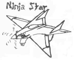
Another concept I came across
was the five-pointed star like the instrument used by the Ninjas of Japan.
A simple concept that would be made of three lengths of aluminum tube for
the leading edges and aluminum channel for affixing the ailerons and elevators.
I dont think rudders would be necessary, just the fins for stability or
a single fin and rudder for better control. Once again, the twin
opposed air-cooled 4-stroke direct drive power comes to mind for simplicity
and I believe 60 hp would make this a 150 kt speed machine in the ultralights.
Yours Sincerely, Terry Baxter
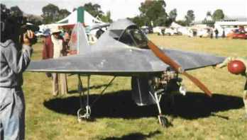
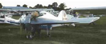
(ed. Thanks for the pictures. I have
included the two of the UFO. The magazine article of the UFO (Useless
Flying Object) says it was designed and built by David Rowe and, represented
his third attempt at getting a round aircraft to fly properly. In
the article he commented it was much slower than it looked and, that after
designing and flying round wings had been interested and novel, but they
did appear to be quite inefficient.
March 25, 2001
TWITT:
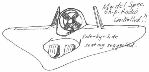
Having come across many large type models which have successfully flown, I cannot understand that a 2-seater flying wing ultralight has as yet never been successfully launched in homebuilt plans or kits. Take the following sketch, although there were no actual measurements; a tandem say with 60 hp could follow, or even 100 hp. It appears to be a standard 3-axis control and would certainly lend itself to a full composite construction. I still think this could be classed as a flying wing!!!
Another was Teledyne 262 of about 7 wing span using a rotoduct. I could not find any details of this model but it was all fiberglass. This would suit a belt reduction, flat 4-cylinder Subaru.
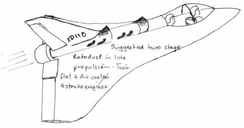
Then there is the AMR XD110 Research scale model for a two seat Bensen Nova training aircraft. First flight was 1969 on a Ross 4 hp driving a multiblade shrouded propeller. Wing span of 7, chord 10, max payload of 80 lbs, max level speed of 300 mph and a stall speed of 10 mph.
The third prototype was
a scale test model in 1976 as a two seat STOL advanced trainer, non-stalling,
double wing delta with sealed control surfaces. Radio controlled
command guidance. Conventional take-off and landing using retract
tricycle landing gear. A later version with twin rotoducts buried
in the aft fuselage was scheduled after 1976.
Regards, Terry (ed. Thanks for the follow-on letter showing
us more of what you have found in the way of models that, like many other
things, never made it into a production stage. This seems to be typical
of many commercial projects when it is found there is really no market
either in the private or public sectors.
|
 ......
![]() ...5/11/01
Back Home...
...5/11/01
Back Home...![]()