|
Which Way The World's Next Generation Airliner? A Look At The Past, The Present and The Possible! By Joe Mizrahi (Reprinted with the permission of Wings, April 1999, Vol. 29, No. 2, Sentry Magazines, Granada Hills, CA, pp. 8-19. Thanks to Paul Spatrisano of Bend, Oregon for obtaining permission and providing the material to TWITT.) |
 |
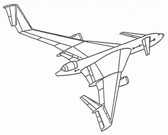 |
| ABOVE: This is the most promising future airliner both aesthetically and in terms of economical operation. The BWB concept actually transforms John Northrop's historic flying wing proposition into tangible reality. Cleaner, less expensive to build, stronger, quieter, easier to handle and still within the parameters of the 80 meter box. Click here for more. | ABOVE: The Boeing C-Wing also known as the "Klingon Battlecruiser" by its two creators J.H. McMasters and I.M. Kroo, departs from the standard tube with wings technology favored by Airbus. Click here for more. |
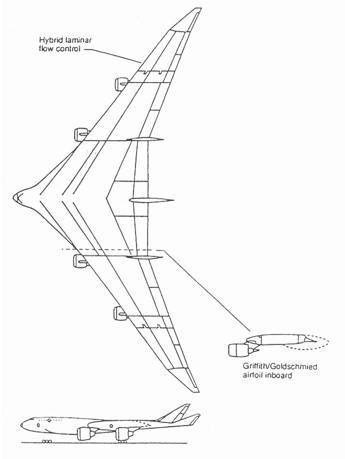 |
LEFT:
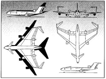
A more conventional shape for the 747 XL dropped the
tube with wings
layout
and substituted a centerbody fuselage with a wing area
of 9,000 sq. ft.
and a span of 300 ft. Its hybrid laminar flow
control outer wing
tips could be folded to reduce span to 170 ft., and the
aircraft,
utilizing
the thick Griffith airfoil with slots on the trailing
edge, plus
Krueger
bug shield leading edge high lift devices, would have
been powered for
four 95,000 lbs. thrust very high bypass turbo
fans.
Accomodations
for up to 800 passengers (50 abreast) would be provided,
and airframe
encompassing
the 1,400,000 lb. (takeoff) weight would have been
largely fashioned
from
composite materials.
ABOVE: C-Wing proposal compared to that of conventionally shaped transport of comparable 600 passenger capacity, shown in black. This version has sharply reduced fuselage and wingspan, while absence of horizontal taile easily allows it to fall within the confines of the necessary 80 meter box, above which aircraft size leads to gate, runway and taxiway restrictions. |
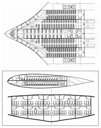
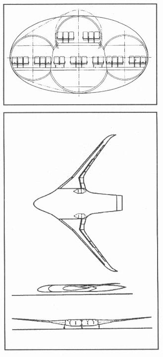 The
minimum wetted area for a given volume is a
sphere. The designers
of the BWB airliner began with cylindrical pressure
vessels in their
initial
layout (top drawing) and gradually pressed down until
they had a
flattened
disk with wings (bottom sketch), its engines on the
trailing edge, just
outboard and to the rear of the centerbody. The
minimum wetted area for a given volume is a
sphere. The designers
of the BWB airliner began with cylindrical pressure
vessels in their
initial
layout (top drawing) and gradually pressed down until
they had a
flattened
disk with wings (bottom sketch), its engines on the
trailing edge, just
outboard and to the rear of the centerbody. |
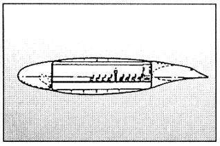
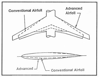 ABOVE: Comparison views of the conventional airfoil (dotten lines) with that of the advanced Griffith airfoil. BELOW:
Cross-section
view of the C-Wing depicts passenger cabin profile of
centerbody. |
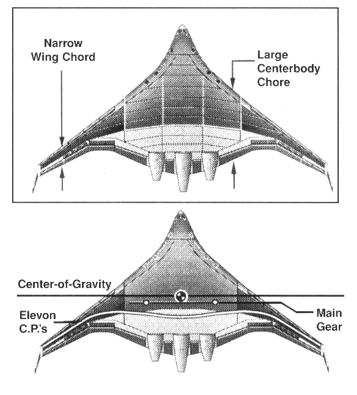 |
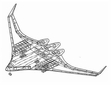
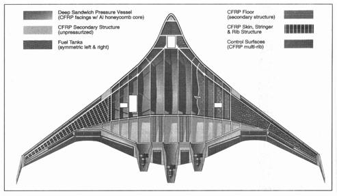 ABOVE: One of the beauties inherent in a BWB airliner is it strength. It readily absorbs both cabin pressure and wing bending loads, and in recent tests in the Stanford University wind tunnel, a 6% scale model easily passed all extreme flight envelope tests. LEFT: The BWB concept reduces the load on the outboard wing section airfoils, while the large centerbody chord provides enormous strength, requiring a much low sectional lift coefficient. This reduced lift demand allows the large thick profile of the centerbody to hold passengers and cargo, without exacting a high compressibility drag penalty. Due to its shape and structure, typical shocks evident on the thinner outboard wing panels become very weak on the centerbody. Ahead of this shock, airflow is supersonic; behind it, the air slows and that sub-sonic area is highly suitable for engine installation. The low effective wing loading of the BWB and its beneficial trim effect means that no exotic high lift system is necessary; only leading edge slats are necessary on the outboard wing, with all trailing edge devices made up of simple hinged flaps which double as elevons. |
 |
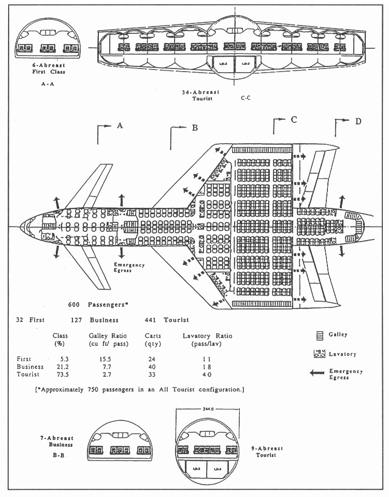 |
| ABOVE: Double-decked BWB interior is configured for ten 150" wide passenger cabin bays, at least 74" high on the upper deck and 84" on the lower deck. Layout is shown from top in in the upper drawing and from the side and front in the lower. Windows are located along the leading edge of each cabin bay, with a promenade aisle curving around and back from the forward flight deck. Galleys and lavatories are located aft. Entrance and exit to the interior is via main cabin doors forward and through doors aft of the rear spar. Cargo bays are located outboard of the passenger cabin, with pressurized fuel tanks outboard of them. Location of the 3 engines to the rear radically minimizes cabin noise. | ABOVE: Interior of the C-Wing design demonstrates that most passengers in coach class are carried within the wing centerbody, leaving the tube portion of the fuselage for business and first class. This forward tube portion, with its canards, has a much smaller diameter than the fuselage of the conventional large body airliner. |
|
With the advent
of
the rectangle,
and then the tube with wings, twin characteristics of
airliners and
commercial
flight since the early Twenties, airline manufacture has
adhered to a
well-established
pattern. Whether a Ford Trimotor, Douglas DC-3 or
-4, the long
line
of Boeings up through the 777, and the entire Airbus
family, passengers
have entered a more or less long cylindrical tube, which
given enough
push
(jet engines) or pull (propellers) has then sped them
away to their
various
destinations. The C-Wing Klingon Battlecruiser To paraphrase
John
McMasters
of the Boeing Company, "innovation for it own sake can
be a great waste
of time, but individuals with a sufficient depth of
knowledge in more
than
one technical discipline can, working in teams, exploit
the unorthodox
to create a very workable design. Additional weight and
more
fuel necessary
to transport the same payload just as far will probably
doom the C-Wing
alternative, but when Boeing absorbed McDonnell Douglas,
they also
acquired
the thinking of three more innovative design engineers,
R.H. Liebeck,
M.A.
Page and B.K. Rawdon, who were working on the Blended
Wing Body (BWB)
transport
of the future. (The remainder of the article covered the history of commercial airliners from other countries, and it included a large number of very good pictures of these aircraft.) |
Back to Top
Back
Home...![]()