New address for Michael Mangenot is obccz@yahoo.fr
|
|
|
|
|
|
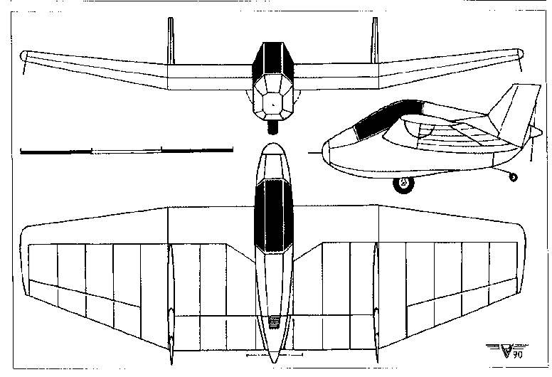 |
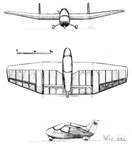
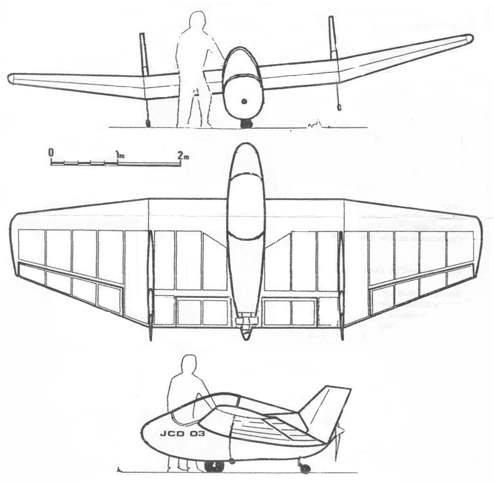
This aircraft has been designed by Jean Claude DEBREYER and is now manufactured and marketed in kit form by the company Air Est Services in Marley, France. 3-view drawing of prototype JCD-02 by Philippe Vigneron. Specifications for the JCD-03: Span
7.2 m
|
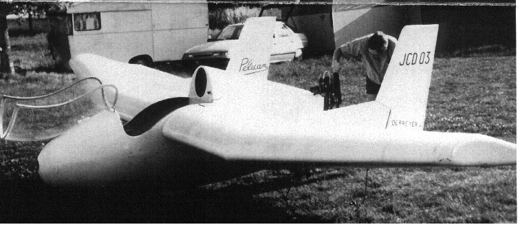 |
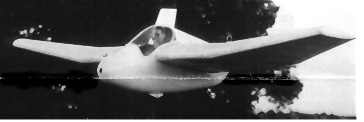
Pictures
of production aircraft JCD-03. Photos by Air Est Services.
Main Chord
2.0 m
|
 |
Landing Speed
45 km/h
Take-off Run 150/200 m Endurance 3 hours Fuel Consump. 3 ltrs/hr Structure -Wings Foam & Dacron Fuselage Composite materials |
FOR MORE PICTURES OF THE "PELICAN", CLICK HERE TO SEE WHAT KOEN VAN DE KERCKHOVE HAS ON HIS 'NEST OF DRAGONS' SITE.
| The following material was extracted
from the daily "Nurflugel" mailing list comments made about the PELICAN
over the past several weeks. If you are a member of the mailing list,
you have probably read all of this before, but if you are new to the flying
wing movement and haven't heard about the PELICAN, please read on.
October 4, 2001
Koen VAN DE KERCKHOVE (nestofdragons@hotmail.com)
Subject: Pelican (rumors?) Hello everybody, It is not my style to tell rumors, but this one
is nurflugel-related and might be interesting to some of you. Somebody
mailed me that Michel Mangenot, the man behind the production of the Pelican-kits,
is planning to retire. I haven't got a confirmation yet, but I know
that Michel Mangenot is not one of the youngest. So it might be true.
Koen (a bit emotional after receiving the retirement-message)
October 11, 2001
From: Mike Lee (rmlee98@pathwaynet.com)
Subject: Re: Pelican (rumors?) I have had several emails from Michel, I keep
pestering him for plans. I would encourage everyone to write him
and inquire about plans. Without the molds the fiberglass work would
be difficult to duplicate, but perhaps a redesign in wood and fabric is
possible too. Would buy the other kit, I think it is reasonably priced,
but the shipping to the US would be the killer, same with his molds, not
practical except for someone with big bucks.
October 24 2001
From: warren bean (warrenbean@austin.rr.com)
Subject: Re: translation Pelican stuff So any comments on the Pelican design philosophy? If I understand the various translations correctly the main points are these: 1. A thin high aspect ratio wing will be heavier than thick low aspect ratio wing. (I assume that the fact that either have to carry a load about equal to the dry weight of the craft has some impact on this.) 2. If the goal is to gain altitude under minimum power, than a wing with aspect ratio 4 was preferable over a high aspect glider type wing because lower weight of the shorter thicker wing is preferable over higher L/D of the higher aspect ration thin wing. In general are these statements true? Can they
be quantified?
October 24, 2001
From: Koen
Subject: [nurflugel] translation Pelican stuff I would like to thank all who did an effort to
translate the French text. I hope that some of you can use the translation
text in their site. I will in mine.
(This was a reply from J.C. Debreyer answering some questions put to him by Koen VAN DE KERCKHOVE. Koen provided the 3-view seen below.) (ed. This is the translated text Koen was referring to in the message above. Translated by Marc de Piolenc.) The JCD02 was the Pelican
prototype, made of wood, equipped with a Peugeot 125 cc motorcycle engine
and a 69 cm diameter propeller. Weight 60 kg empty. It flew well but its
strength was probably inadequate. The JCD03 was practically the same design,
but much more solidly constructed of epoxy/glass laminate. Heavier (80
kg) and provided with a single spar set further forward on the
(ed. With all of the above on the table, a series of discussions were started by several participants. I have tried to present the more interesting questions and answers as they pertain to the Pelican, so apologize in advance if there is an occasional break in the thought thread.) October 25, 2001
From: Mike Lee (mikelee@chartermi.net)
Subject: Pelican Flight Does anyone know where the CG should be on the
Pelican?
October 25, 2001
From: Ron Taborek (taborek@netcom.ca)
Guelph, ON, Canada Subject: Re: Pelican Flight There have been some
questions about the balance between horsepower and wing span for an aircraft
like the Pelican. There is a technique for calculating such a balance
for an aircraft design. One example of it is described in Airplane
Design Part 1.- Preliminary Sizing Of Airplanes, by Dr Jan Roskam.
October 26, 2001
From: Ronen Atour-Gad Yehiav (ryronen11@speedy.co.il)
Subject: Re: Pelican stuff-CG does not compute Here it is, step by step: (ed. This is Ronens
reply to Mike Lees questions, indicated by the
Cl has no point of operation - it is a coefficient, not a force. CG does not change with AoA. For most parts, until stall, Nor does the lift move around that much.
Mostly lift is at around 25% of chord. But - which chord? The Average Aerodynamic chord.
HUH? How so?
Frankly, neither do I. I don't think I understand your statement above...
CG location depends very little on the type of airfoil. Trim may depend on it, but not CG.
It has nothing to do with figuring any distances, apart of showing you where the average aeronautical center is located. Know that, and you can set CG easily. So, why a flying wing would be different?
No problem. And there is no more complicated
theory for flying wings than for any other types of airplanes. Not
until you try to pry the last 1% of performance improvement!
October 26, 2001
From: Mike Lee
Thank you for your well
thought out response, I'm sorry, but if anyone can answer the questions
I posted about the Pelican, I would still like to read them. I just don't
seem to have the ability to plug this stuff into some graph and come up
with an answer that I would have any confidence in. Particularly when there
seems to be two or three different bell curves, which must intersect, with
figures in #, Mph, Hp, weight in Kilograms, etc., up and down four sides
of a graph. I can stare at that stuff for hours and not come up with any
thing that makes sense to me. I guess that is why I didn't become an engineer.
October 28, 2001
From: Hugh Lorimer (lorimer@alpbach2.fsnet.co.uk)
Subject: "PELICAN" Hi Andy, I have
just spotted J.C. Debreyers Pelican on the TWITT site. The design philosophy
and layout would appear to be similar to my Sgian Dubh (SD), although the
SD is bigger and heavier. There doesnt seem to be an "e" address? and
I wouldnt mind a wee chat with him.
October 29, 2001
From: Koen
Subject: Pelican stuff for Mike Lee (and all others) 1) I am happy to see you found your way to the nurflugel mailing list. This group is filled with professionals AND with model builders, bookworms and enthusiasts. You will find a lot of data there or guidance towards usable info. I will from now on contact you through the list. If I make a technical mistake, I am sure that others will correct me. 2) DOOOOOON'T GIVE UP ON THE PELICAN (or the unswepted flying wings). I don't know if you are a patient type, but the last few months I found data about the Pelican, which was unknown for many years. I do think that I have a good contact with JC Debreyer. I do think that I might get the info you wish. I am close to getting pictures. I do hope for you that there are also construction pictures. 3) I saw your questions on the list. Pity, you didn't ask these questions the first time I was writing a letter to JC. I could have asked them. Well, I will put them in my next letter. I will search my own pictures too to see if I have a picture of the technical part of the Pelicans kit. I didn't place all the pictures on the Nest of Dragons-site. 4) It is a pity that the JCD02 was constructive less good than the JCD03. I still believe that a JCD03 - similar design can be made with wood, but I am not the person to ask how and I am not sure that you will be possible to keep the weight as low (when making the same strength as the JCD03). Things like this get me scratching my hair too. Not a engineer too. 5) About the design: a lot of other low power engined designs do indeed look like gliders with long and narrow wings. They started their design from the idea to get a low as possible sinkrate. If the sinkrate is low, the engine needs not much power to keep the airplane at the same height. This point of thinking is very common. JC Debreyer began his idea at another point. He wanted to reduce the weight at the best. Long wings are heavy wings, that is right. Choosing a high airfoil makes it possible to make a lightweight spar. According to Jack Lambie's book I think to recall that a spar with double height is 4 times stronger ... or was it stiffer. Damn memory... Can anybody correct? Well, once you have a ultra low wing loading you might not have the best possible low sinkrate (the drag of the Pelicans wing is high due to its high airfoil), but it gives you a chance to use a light engine too. I still don't understand the link between low wing loading and low power. I know about low wing loading and low speed, but I never saw this other relation explained. Anyway, JC did design his JCD03 that way and it did work. 6) Further development of the Pelican: I do think
that JC Debreyer has a very good design. It is compact, not much parts,
little construction costs, little flying costs. But it could use
a larger engine and a larger prop (most common comment). How can
one do that? Well, I don't suggest to use a front placed prop, but I suggest
to use a ducted fan. Place the engine central, make a duct from the point
after the spar to the end of the fuselage. Use this duct as a constructional
part so it gives rigidity to the fuselage. The prop might still be small,
but the efficiency of the prop is higher. The engine placed after the spar
may be heavier, due to the shorter distance to the CG. A rudder might be
placed in the ducts end to ensure efficiency at low speeds. But you
loose in the basic design of the Pelican, because you add weight. And this
might get you into a totally new design which ask you look again at the
size of the wings and the wanted perform-ance (speed, low costs in flying
or shorter take off). I myself would be super happy if I simply could
build a Pelican like it is. But I just wonder how it would perform
when a central engine would be placed (like Mr. Mangenot suggested first
at my visit to the firm).
October 29, 2001
From: Mike Lee
Regarding the larger
engine, the engine I have in mind weighs about 70#, and this is quite
a bit more than the 10Hp JC uses. However, we have to redesign the thing
anyway, so just move the Pilot forward. I weigh 3x more, or less (actual
less, than the difference in weight of the engines) so I move forward a
little to keep the CG in the right spot, (if we know where that is supposed
to be). I was real surprised no one could really look at the design and
say, well it should be about at the spar, by the look of things. And yes
I know what is Mean Average Cord, but not all designs seem to follow the
25-30% of MAC, and the reasons are unclear to me. I have seen a design
with a constant cord wing and pusher configuration, with the pilot out
in front of the Leading edge and the CG was indicated in the picture to
be about under his Butt, several inches in front of the leading edge.
Totally new concept to me, I have been building RC for 35yrs, and I never
flew anything like that, but I have never built and flown a Pusher either.
October 29, 2001
From: Koen
Hello Andy, Sure am happy that the
Pelican gotten so much attention lately. It has been a very unknown airplane
the last years. I am glad to be opening doors for the Pelican. It is a
too much interesting type (referring to the idea of "a plane for the man
of the street" and to "budget flying") to go by unnoticed.
October 29, 2001
From: "DavidRSw" (DavidRSw@msn.com)
Subject: Re: Pelican stuff for Mike Lee (and all others) Koen wrote:
In the past, this has been true, but not any more. A 15 meter sailplane wing can be built of composites and the wing weighs only 75 lbs. ±7 G's, all controls, pushrods, mixers, flaperons, ailerons, & spoilers. Add a T-tailed fuselage if you must ;-) and it weighs 135 lbs. empty. You then have a 80 ft./ min. sink rate, 23 mph stall, Vne ~100 mph, 35:1 glider. With 35:1 at 39 mph, that means 9 lbs. of drag. Think we might find a motor & propeller that could produce 9 lbs. of thrust with low fuel burn? ;-) Composites can be wonderful or the devil. > Well, once you have a ultra low wing loading . . . We can now-a-days get high lift and low drag from highly cambered airfoils. The US4 airfoil is a little over 17% thick. The wing has 7 different modified US4 airfoil changes along the 15 M. span, each optimized for low drag at its design Cl for an elliptical lift distribution. No wing twist at 0° flap and 6° of twist at 12° of root flap setting. At 12° of flap, the airfoil at Re 1,000,000 computed Cl is 2.1 with a Cd of .018, a Cm of -.4, at a AOA of 6°. The power of X-Foil and ASWing are amazing. > I know about low wing loading and low speed . . . Wing loading varies between 2.18 - 2.8 lb/ sq.
ft.
We'll see how it flies in late Nov. or early Dec.
With higher amounts of drag, we would need more h.p. to over come it.
October 30, 2001
From: "Ronen Atour-Gad Yehiav"
Subject: Re: Pelican stuff for Mike Lee (and all others) There are many more considerations then minimum
thrust for choosing an
> In the past, this has been true, but not any more. . . . Up to here, correct. However, There is still
power required to accelerate the thing to TO speed, where the drag can
easily be 3, 4 even 9 times larger than at maximum glide angle speed, or
minimum, sink rate speed.
> Well, once you have a ultra low wing loading . . . Low wing loading can actually reduce induce drag
much more than the increase in the drag efficiency coeeficient that results
from the decrease in AR. The problem is that increased wing area causes
an increase in parasite drag, which increased AR does not. Actual
TO, landing and sink performance are MORE influenced by the wing area than
by the AR.
> We can now-a-days get high lift and low drag from highly cambered airfoils. Yes, we can, but why should we? > The US4 airfoil is a little over 17% thick. The wing has 7 different . . . . This is a very elaborate strategy. Too elaborate. Goes totally against the KISS - SAAL principle. Ronen.
October 30, 2001
From: Koen
Subject: Re: Pelican stuff for Mike Lee (and all others) Hello Mike, When you add a lot of
weight to a design, you must keep in mind that you are also adding a lot
of needed speed to get airborne. So you get a higher landing speed
(and that is not very good for a beginners airplane) and you increase the
take off run (I always love to be airborne before the fence
;) ).
Keep that brain spawning wings, Koen PS: Scanning might take a time.
October 30, 2001
From: Koen
Subject: Re: Pelican stuff for Mike Lee (and all others) Hello everybody, Just to mention that
I found several pictures that I didn't use in my Pelican page. I will scan
them and place them at the files section of the Nurflugel
mailing list.
Keep that brain spawning wings, Koen
October 30, 2001
From: Ronen Atour-Gad Yehiav
Subject: Re: Re: Pelican stuff for Mike Lee (and all others) > PS2: Later I will try to make a mail that can explain . . . Much simpler - print it on a cardboard or Manila
paper, cut it, and hang it from 3 points to find the center of the area,
which - in uniform materials - is the center of gravity. this will
give excellent approximation of where the Neutral Point is.
> No one could really look at the design and say . . . Just mentioned a method - mot as simple as looking, but not much more complex... > Average Cord, but not all designs seem to follow the 25-30% of MAC . . . A Canard, perhaps? Not much sense, otherwise... Do you have the drawings on a computer? Ronen.
October 30, 2001
From: Norman Masters (philadelphus@reanet.net)
Subject: Re: Pelican stuff for Mike Lee (and all others) Mike Lee wrote: > Regarding the larger engine . . . . . IMHO This issue of balancing the weight of the engine by moving the pilot forward is the strongest argument for pusher props. Poor visibility is usually a problem for flying wings and, as far as I'm concerned, the best way to fix it is to get the pilot's eyes out in front of the wing. > I was real surprised no one could really look at the design . . . . Simply guessing at the CG from looking at the planform is damn dangerous no matter how experienced you are! Since you have 35 years of RC experience I assume you know the graphical construction method to find MAC. That method works pretty well for wings without sweep and would be an adequate first approximation here. Once you have estimated the AC graphically you can ASSUME a point 2 to 5 percent forward as the correct CG. > And yes I know what is Mean Average Cord . . . . The CG must have been marked wrong. The aero-dynamic center of an airfoil will ALWAYS be near 25% chord (at subsonic speeds), on an unswept all-wing the neutral point can't be very far from the AC because the control surfaces don't have enough leverage to compen-sate for an out of trim condition. On a conventional design the horizontal stabilizer causes the NP to be farther aft than the wing alone, and that's why they can be balanced with the CG aft of 25%MAC. A canard has the opposite effect, moving the NP forward. October 30, 2001 Subject: Re: Pelican stuff for Mike Lee (and all others) Hello Mike, > Average Cord . . . . Was it any chance the Haig Minibat or a Marske
Monarch or Pioneer? They have forward sweep. If you only see a drawing
with the cockpit, you will get a CG at the leading edge that is right.
But you need to keep in mind the forward shape of the wing.
1) Find top view of wings.
Now for the Pelican. Use the technique on
both sections. You get two points. Now you need to calculate a bit. Calculate
the area of both sections. Now use some logic. If both sections would be
as large, the true AC will be in half of the distance between these two
points. If the inner section is larger the AC will lie closer to the point
of the outer section (because the point of the inner section has more "weight"
(just a expression to let better understand)).
October 30, 2001
From: Norman Masters
Koen wrote: > Guys, if I am wrong here, please, correct me. I am using this technique for two years in my sketchbook. A verbal description of this procedure is always difficult. I've seen it tried many times and it's never satisfying. Also Koen, it sounds like you may be using more lines than you need. These two pages from the Experimental Aircraft Association show the how to locate the AC with construction lines. http://www.eaa62.org/technotes/cg.htm
> About the most forward distance of the CG of the AC . . If you're thinking of Martin Hepperle's page
the link on Doug's page is out of date because Mr. Hepperle recently moved
to a new ISP. I have the currant link on my page: http://www.gj.net/~nmasters/index.html
November 3, 2001
From: Joachim Bergmeyer (jbergmeyer@t-online.de)
Subject: Pelican stuff (mine flies :-) Hi, Just for fun, to use up a spare hour and to please my four-year-old I made today a Pelican model out of Depron (extruded polystyrene, normally used as thermal insulation behind wallpaper). It has 10" of wingspan, weighs 4g and flies straight, level and astonishingly fast in my living room. See two pictures: http://jbergmeyer.bei.t-online.de/Pelican002.jpg
I have included a standard
AA cell for size comparison. The picture quality could be better, but my
digital camera is a very simple one.
Regards, Jochen
November 3, 2001
From: Mike Lee
Subject: Re: Pelican stuff (mine flies :-) That looks really nice. I bought some Coraplast,
and some downspout, yesterday when I was in the big city, and was
thinking of doing a rough 1/4 scale proof of concept r.c. model. I've used
the stuff
|
|
|
|
|
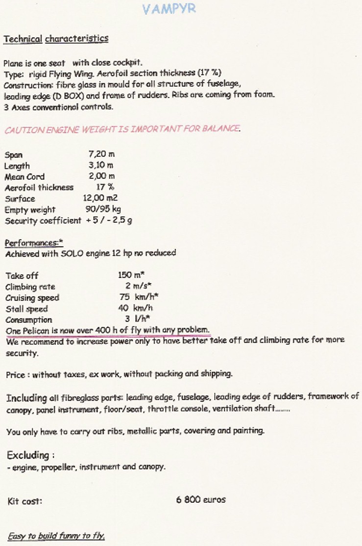
 chord,
the 17% ABRIAL section was not accurately followed and caused me to lose
the advantage of the 12 horsepower of the SOLO 212 engine. The aft position
of the engine made it impossible to increase the engine's weight, hence
its power. The ground clearance of the propeller did not allow a large
propeller to be easily employed, which made for long takeoff runs with
the 74 cm propeller. The purpose of these two flying wings was to verify
that for flight with minimum power, an aspect ratio 4 wing was needed,
and not the narrow wing of a glider. To gain altitude it is better to save
some weight than to increase aspect ratio. And as it happens, a narrower
wing is a heavier wing. That is also the reason that I preferred a 17%
thick wing instead of 12%. Struts would have had the same effect. The single
wheel landing gear also allows a consider- able weight saving (the forces
are transmitted directly to the pilot's buttocks, without extra material).
Alas, the balance wheels were set too far aft, which made ground handling
difficult in a crosswind. This airplane was very easy for anybody to fly
who had 20 hours on a conventional airplane.
chord,
the 17% ABRIAL section was not accurately followed and caused me to lose
the advantage of the 12 horsepower of the SOLO 212 engine. The aft position
of the engine made it impossible to increase the engine's weight, hence
its power. The ground clearance of the propeller did not allow a large
propeller to be easily employed, which made for long takeoff runs with
the 74 cm propeller. The purpose of these two flying wings was to verify
that for flight with minimum power, an aspect ratio 4 wing was needed,
and not the narrow wing of a glider. To gain altitude it is better to save
some weight than to increase aspect ratio. And as it happens, a narrower
wing is a heavier wing. That is also the reason that I preferred a 17%
thick wing instead of 12%. Struts would have had the same effect. The single
wheel landing gear also allows a consider- able weight saving (the forces
are transmitted directly to the pilot's buttocks, without extra material).
Alas, the balance wheels were set too far aft, which made ground handling
difficult in a crosswind. This airplane was very easy for anybody to fly
who had 20 hours on a conventional airplane.
 Koen
added: With this letter JC Debreyer answered my questions about the
different types of Pelican and why he choose to use a 17% high airfoil
and not a lesser draggy 12% high NACA 23112. I still have the idea
that the Pelican is a extraordinary design. It brings a closed cockpit,
a stable platform, a extraordinary view and a eye-catcher to the beginning
pilot. Man, how I will hate it if this little jewel's molds will
get lost in one's attic.
Koen
added: With this letter JC Debreyer answered my questions about the
different types of Pelican and why he choose to use a 17% high airfoil
and not a lesser draggy 12% high NACA 23112. I still have the idea
that the Pelican is a extraordinary design. It brings a closed cockpit,
a stable platform, a extraordinary view and a eye-catcher to the beginning
pilot. Man, how I will hate it if this little jewel's molds will
get lost in one's attic.