|
The following items were extracted from some of the material we have available in the TWITT library. They are only a small portion from each of the articles provided by our members over the years. Click here for a complete bibliography of this material. |
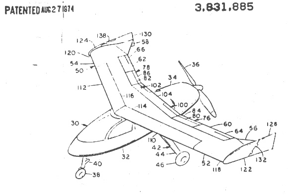
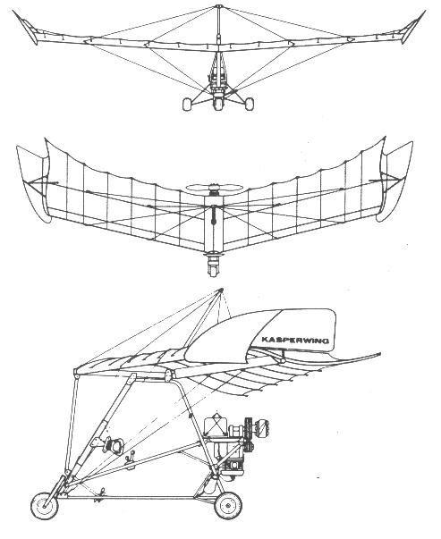
Undercarriage has three wheels in tricycle formation; no suspension on any wheels. Push-right to-left nosewheel steering independent from yaw control. No brakes. Aluminium-tube framework with optional pod. Engine mounted below wing driving pusher propeller. Dacron used for covering wing and underside of mid-chord spar. The Kasperwing 1-80 was designed by W. Kasper in collaboration with Steve Grossruck and the prototype constructed in 1976. The Kasper effect allows the 1-80 to make vertical approach to landing while remaining stable in all three axes during a descent at 160ft/min. with a 154 lb. pilot. It has a twin spar wing, each wing having six ribs folded into a flattened 'S' shape to give a stable profile. The Kasper can be summarized as twin rudders carried on tripod struts at the extremity of each wing in such a way that the rudders are also used as vortex generators and as air brakes. Powered by Zenoah G25B, 25 hp. engine with a max cruise speed of 45 mph. Length 10', span 35', chord 5.6', height 11' and total wing area of 180 sq. ft. Source: Cascade Ultralites 1983 promotional brochure. |
United States Patent # 3,831,885 This is Figure
1 from the above patent. It is a perspective view of the aircraft
at rest, with all the directional control airfoils and vortex generating
and control airfoils in their neutral positions.
|
by Witold A. Kasper The
wingtip rudders are the second roll control system which also have the
dual function of yaw control. In order to balance out the aerodynamic
force on the deflected rudder, an aerodynamic balance forward of the hinge
line is provided. (Fig. III-8)
|
|
Kasper
wrote: "The shape of the wing has to be rectangular, not tapered.
The reason is that pitch control is affected by changing the spanwise lift
distribution. We must have lift at that part of the wing where the
elevators are located. The wingtip stabilizers help to obtain an
ellipitical lift distribution. When the elevators are moved up or
down, this ellipitcal lift distribution changes to a more or less triangular
one, causing a considerable shift of the center of pressure inboard or
outboard and, due to sweepback, forward or rearward."
The figures at the left show, from top to bottom, normal horizontal flight, nose down flight, nose up flight and, rolling flight. Kasper used the bird symbology, since he felt his aircraft were as close as any yet designed to simulate controlled flight like the birds. He had extensively studied birds and insects throughout his life trying to find why they flew so well and man's inventions did not. Again, Kasper wrote: "The concepts that I have presented are facts, not theories only, proven by flying and testing Flying Wings of my own design. My research also serves to explain why earlier designs of flying wings and tailless airplanes by others, both in this country and Europe, were failures and based on wrong assumptions. I hope my fellow airplane and glider designers are open-minded enough to accept what I have offered as a contribution to their search for a safer and better air vehicle. Let us fly like a BIRD!" |
Back Home...............................................Back to Index.......................................................11/29/98