|
The Horten Tailless Aircraft by K.G. Wilkinson, B.Sc. D.I.C. Horten I, II & III
|
|
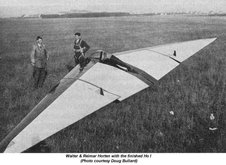
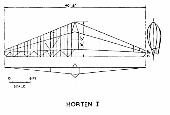
This was built
at Bonn during the year 1931-1932 and had a flying life of about 7 hours.
It had a span of 40 ft. and a wing loading of 2 lb/sq.ft. The control
system comprised a control flap giving elevator control and normal ailerons
at the wing tip. Directional control was by leading edge drag rudder
at the wing tip.
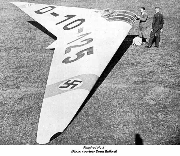
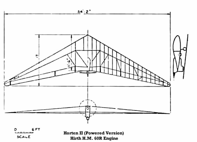
3.3 Horten II This aircraft
was of the same general layout as the H I but with sweepback increased
from 19° to 26° and the lateral and longitudinal control combined
in an elevon. Inboard flaps extending from elevon to center section
were used to increase maximum lift and drag for landing.
Appendix II
The following is a translation of a German report on the flying characteristics of the Horten II and prepared by the well known Hanna Reitsch. Flight Tests of the Horten II, D-11-187 on the 17.11.38 at Ranesdorf The Horten II was tested by Hanna Reitsch (D.P.S. Darmstadt) at the request of General Udet. The type tested was built in 1934 and has since been followed and improved by the types H III, H IV and H V. (The Horten III was successfully flown in 1938 Rhoen competitions and obtained a height of 8,000 meters (26,000); it was destroyed in a hail storm but was flown again in 1939. The H IV and H V were completed in December 1938. The following report on the flying characteristics must not, therefore, be regarded as representing the present stage of development of tailless aircraft by the Horten brothers. The flying qualities do not correspond to present day designs. The following should however be noted: it possesses great static longitudinal stability and complete safety in relation to the spin. Flying Characteristics Since the builders of the Horten II did not have available sufficient raw materials for its manufacture, the resultant construction has made the testing very difficult. For lack of ball bearings the control surfaces are so heavy that measurements of stability cannot be carried out. (A) Cockpit (i) Comfort.
Not exceptional.
(B) Takeoff and Landing Characteristics Takeoff The carrying out of the normal takeoff technique is not recommended because of the long run that results. The takeoff is best carried out with fully back control column until the aeroplane rises from the ground without change of incidence. When two or three meters height is reached the control column may be put so forward so that the aeroplane attains a normal flying attitude. It is thought the long takeoff which otherwise results is caused by the unsatisfactory arrangement of the undercarriage. Landing Landing, even on a small field, is easily made by means of the landing flaps and use of the drag rudders on both sides so that they act as dive brakes. Landing run is normal. (C) Balance and Stability Balance and stability could not be adequately tested because the central column would remain in any position in which it was put because of friction. Static longitudinal stability is good. (D) Controlability and Control Forces Longitudinal Control The motion is strongly damped. Loads are normal. Lateral Control The response is inadequate and unpleasant due to a large negative yawing momet which appears when the controls are displaced. The control forces could not be accurately judged due to the friction and also buffeting on the central column by gusts. This fluttering of the ailerons is probably caused by teh lack of static balance of the central surfaces. The over balance of the controls also gives a feeling of lateral instability which however does no appear in calm air. Directional Control There are upper and lower
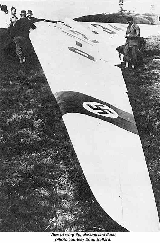
surface spoilers on the outboard wing. When they are operated a response
occurs suddenly. Operation of the directional control suddenly slows
down the inner wing and the aeroplane turns immediately about both the
vertical ad the longitudinal axes.
(E) Turning Flight Turns are only possible with difficulty. That is to say they are impossible with ailerons alone and can only be made using the drag rudder. Maneuverability If strong drag rudder movement is applied, maneuverability is good. The true bank can not be easily obtained (it must be noted that the test pilot could not retract the undercarriage and this would adversely influence the banking properties. (F) Side Slip Side slipping cannot be carried out on the Horten II. (G) Characteristics in the stalled flying condition The aeroplane cannot by any sort of control movements be made to drop the wing or to spin. With the control column pulled right back the machine pitches slightly forward and sinks without reaching a speed of more than 90 kph. (This is a great help in blind flying when the instruments are iced up.) General The above failings are to be taken up with the Horten brothers with regard to further developments of the machine. Darmstadt Airfield 12.11.38 3.4 Horten III The first H
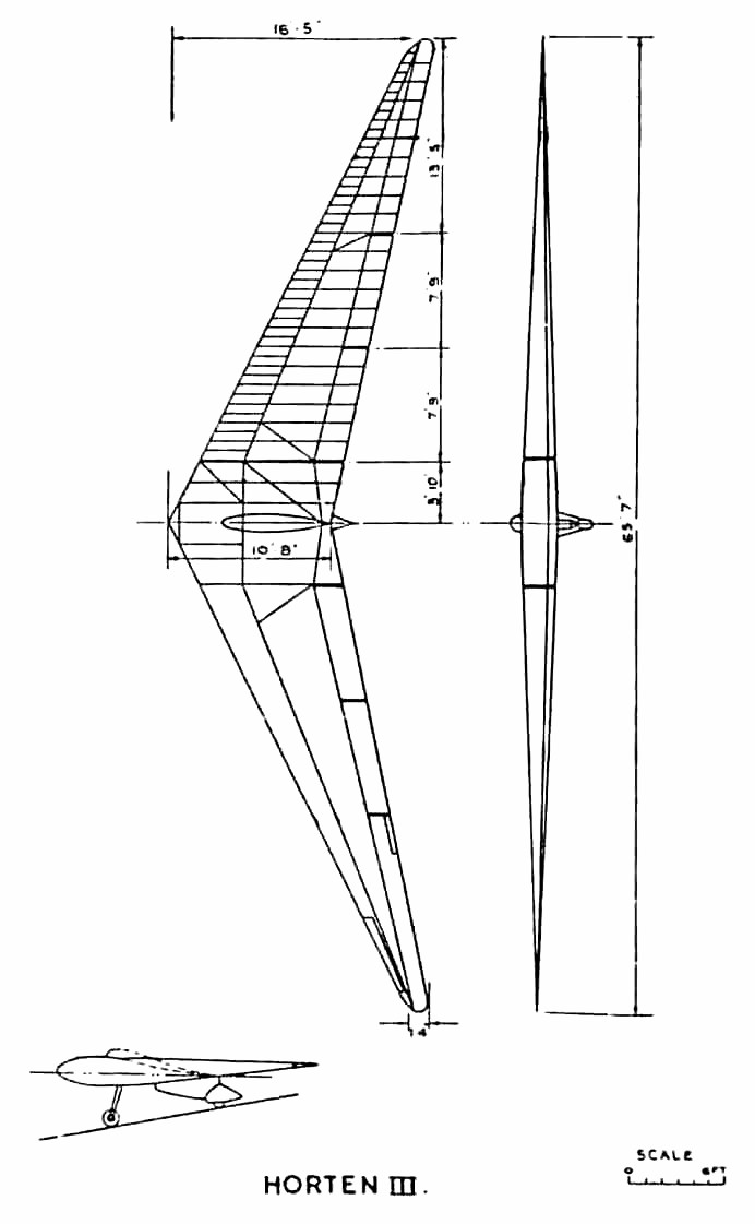
III was built at Templehof Berlin in 1938 and the second (H IIIb) was
built by Peschke Flugzeugban, also in Berlin.
IIIa Original design (Fig. 2) IIIb Similar, but with outer elevon flap not extending to the wing tip. IIIc Type (a), but with a fixed front plane. One of these was built, for the 1938 Rhon contest. Very little flying experience was obtained. The idea was to improve CLmax. IIId Standard wings fitted to a special
center section with 32 hp Volkswagen engine and folding propeller.
The idea was to produce a high performance sailplane with auxiliary engine
for takeoff and climb, which could be shut off for soaring without impairing
the performance as a sailplane.
Performance with power was stated to be:
Ground run
70 meters
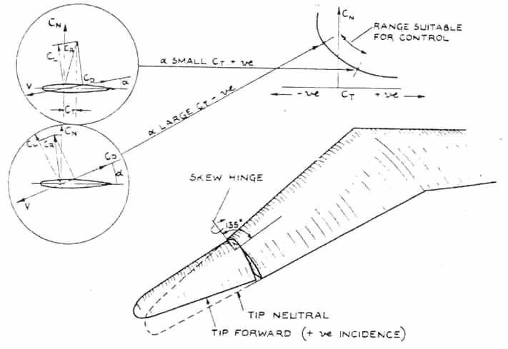
The engine installation was take straight from the Volkswagen complete with exhaust system and electric starter; it weighed 240 lbs. IIIe H III glider with waggle tips. The scheme is sketched in Fig. 26. On this aircraft, remains of which were found at Gottingen, the tips were operated directly by the pilot. IIIf Same as the IIIb, but with prone
position for the pilot. A specimen of this type was found by the
writer at Gut Nierstein with modified controls. The outer flap had
a Frise nose, (as on H IV), spoiler type drag rudders were fitted in place
of the usual leading edge split flaps, and H IV type dive brakes installed.
IIIg Special two-seater center section
with tandem seats. Specimens were found at Zimmern and Hernberg.
This type was used for training purposes.
|