|
3.5 Horten
IV
General
The
H IV represented the Hortens mature thoughts on sailplane design.
The span was the same as that of the H III but aspect ratio was increased
from 10.7 to 21.1, and the control system further developed. In order
to retain their finless wing layout and get the maximum aerodynamic efficiency,
the pilot was put in a prone position with his body in a 27% thickness
ratio egg and his knees and legs in a small leg well, which also supported
the rear skid ( or wheel in the case of the H IVb).
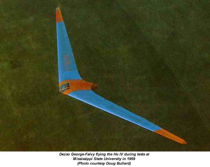
A specimen of
HIV was found at Göttingen in good condition and was brought back
to R.A.E. for test flying. It has completed 500 hours flying since
its construction in 1942, including a cloud flight of 1-hour on instruments;
such a flight demonstrates that stability and control and the comfort of
the prone position must be satisfactory.
Control
The three stage control
flaps were all geared to the spectable type control wheel and operated
on the same general principle as the earlier two flap control on the H
III. The following table gives the (measured) flap movements corresponding
to full control by the pilot.
It will be seen
that the outer flap works principally as up going aileron whereas the climbing
elevator action comes mainly from the middle flap and diving elevator
action from the inner flap. Down going aileron, needed to neutralize
pitching moments, comes from the inner and middle flaps together.
The center and inner
flaps were unbalanced, with round noses, the tip flaps Friese balanced
with a skew hinge giving 39% balance at the inboard end and zero balance
at the tip. This scheme, shown in Fig. 8 (ed. not reproducible)
gave the required aileron yawing moments without making the control flap
at the tip vulnerable when a wing tip scraped the ground.
Drag rudders were of
the upper and lower surface spoiler type placed immediately ahead of the
outer control flap; the upper surface spoiler had a vented web (Fig. 7,
ed.
- not reproducible). To open the rudders the pilot had to press
with his toes, moving the foot from the ankle against a spring loading
on the pedals which gave "feel" to the control. By pressing both
feet together he could open both rudders simultaneously, thus giving extra
drag for glide control. Rudder operation was said to cause no buffeting
of the control flaps. The movement transmission from the pilots
pedal included a cam plate (Fig. 11) cut
to give no rudder movement for negative movement of the pilots foot (i.e.,
pressure on the opposite pedal) and an approximately linear relationship
between pedal movement and rudder projection for positive movement (i.e.,
pressure on the pedal).
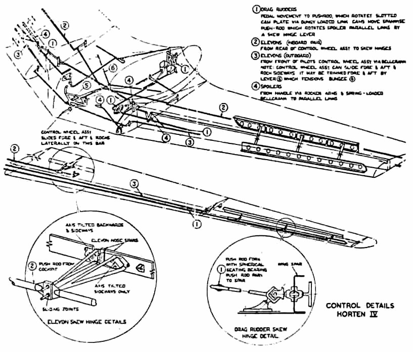
All controls were operated
by push rods, the inner and central flaps and teh drag rudders being moved
by skew-hinge cantilevers; the system is illustrated in Fig. 11.
In the IVb the skew hinge principle was extended to the outer flap operation
also. The method of operating the control flaps was simple to construct
and eliminated all external control horns.
Longitudinal trim was
obtained by an internal bungee spring which can be adjusted to take any
out-of-balance aerodynamic loads on the elevator control.
There were no landing
flaps by large spoiler type dive brakes were provided, which could be used
to give variable drag for glide path control.
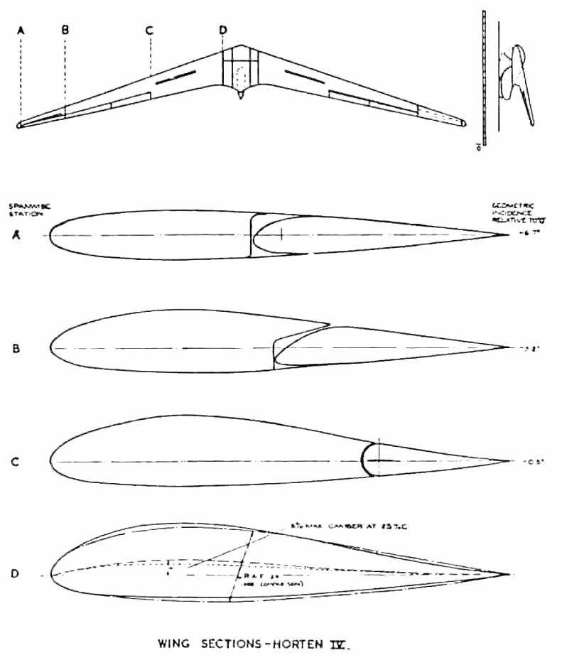
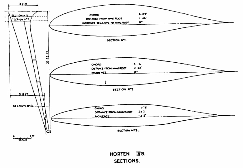
Wing Design
The H IV used reflexed
cambered sections (zero Cmo) of R.A.F. 34 type, changing to
assymetrical section at the wing tip. Sections at four stations on
the wing are given in Fig. 9 and tables
of ordinates in Table II. The Horten method of deriving wing sections
is described later (para. 4.5). Fig. 9 also shows the meaured washout distribution;
this was such that leading and trailing edges were approximately straight
(second power distribution) but this was fortuitous as the actual design
formula was more complicated ( para. 4.2.1).
The large wing dihedral
of 5 percent was used to give adequate wing tip clearance.
Reimar Horten considered that aerodynamically this might be on the large
side but advisable for practical reasons. It should be remembered
that both the H III and H IV have an abnormally low value for the lateral
relative density Uso that unusual values of Lr and Nv would be permissible
without dynamic instability resulting.
Flying Qualities
Performance was measured
by flying the H IV against the D 30, a conventional high performance glider
which had been carefully performance tested by D.V.L. to form a standard.
The essence of the method was to two both aircraft up together and let
them glide down from about 10,000 at a series of speeds, measuring the
relative height photographically, at intervals. From these tests
the best gliding angle of the H IV was found to be 1 to 37 and the minimum
sinking speed 1.7 ft/sec. Minimum sinking speed was slightly less
than the D 30, but at high speeds the d 30 was better.
Scheidhauer, Hortens
chief test pilot, has done the majority of the flying in Horten IVs (about
1000 hrs) and his comments are worth recording. H is a strong advocate
of the prone position - in his own words it has nothing but advantages.
All H IV controls he described as very light, he flew the glider with two
fingers. The elevator was apparently rather sensitive compared with
the aileron but not unpleasantly so. Aileron application produced
no adverse yaw - a definite improvement after the II and III - and
could reverse a 45 degree banked turn in 5 secs. at 70-90 mph, which is
better than the average sailplane. Longitudinal stability he thought
satisfactory but he commented on a wiggle which was produced by flying
through gusts; this is apparently a sharper pitch response than for a conventional
sailplane, but well damped, quite harmless and requiring no corrective
action by the pilot. A true stall could not be produced with normal
elevon adjustment because of increasing static stick fixed stability at
the stall, which used up available elevator power before the wing tips
were stalled. Spins could only be produced by applying full aileron
and rudder with the stick hard back; recovery was easy.
Stability and controllability
on tow were excellent. Scheidhauer described a competition in which
a number of sailplanes were aero-towed form Grunau through the very turbulent
air in the standing wave from a nearby mountain; the rough air had to
be negotiated on tow to get to the area of rising currents. All the
instructors from the school at Grunau were flying conventional sailplanes
and broke their two lines without exception. Scheidhauer in his H
IV managed to get through and soar in the standing wave. He attributed
his success partly to his own skill and partly to the good controls of
the H IV plus his ability to use the tip rudders together to check surging
in the tow rope.
Take-off seems to present
some problems to a pilot new to the aircraft. It seems that the short
undercarriage base, responsive elevator and small wing tip clearance can
produce a very erratic take-off if the pilot is not smooth and precise
in his control movements.
Structural Features
Construction followed
the normal Horten practice, but the wing panels were made with detachable
tips of sheet clektron. This was necessary because the narrow chord
at the tip made accurate construction in wood very difficult. The
center section was of welded steel tube, with perspex (sp.) nose
and a large jettisonable access cover behind the main spar (Fig. 6) (not
reproducible).
The front skid was retractable
and fitted with a wheel which automatically dropped off as the skid retracted.
The pilots harness
was modified from the original version shown in Fig. 6, being a single
broad strap passing under the buttocks. This was released by the
same handle that jettisoned the access cover. The pilots parachute
was stowed in a pocket on the cover and connected to the pilots harness
by short straps. In this was the pilot was relieved of the weight
of the pack, which would otherwise have caused some discomfort on a long
flight.
Equipment
Flying instruments included
a low reading A.S.I. driven by a venturi, electrical turn and bank indicator,
sensitive variometer, high reading variometer, altimeter and clock.
Oxygen equipment comprised
two bottles, pressure gauges, reducing valve and economizer, and provision
was made for electrically heated clothing. Ventilation was under
the pilots control.
Prone Position Bed
(ed. - Several lines
were missing here) . . . . well could be adjusted for varying
pilot size and a chin rest with adjustment for height was provided.
The pilot was prevented
from sliding forward byh shoulder rests and the reaction of his thighs
against the knee well.
Comfort appeared to
be satisfactory when we tried the bed but elbow and shoulder movement was
restricted which constrained one to stay in the same position all the time.
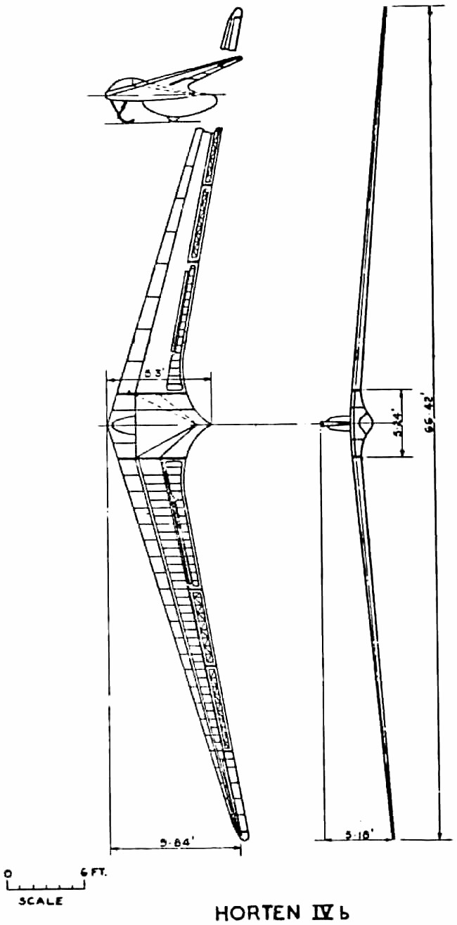
3.6 Horten
IVb
General
Superficially the IVb
resembles the IV very closely but the aerodynamic
changes were a fundamental experiment. The Hortens intended to
produce a laminar flow sailplane with superlative high speed performance
- in this they were partially successful but they sacrificed too much on
the stability and control to make the venture a real success. Production
had been started, prematurely, at the rate of about two a month.
Aerodynamic Design
Wing sections were derived
from the Mustang section which had been measured by D.V.L. for captured
aircraft and tunnel tested. The Hortens were excited by the low tunnel
drag figures and designed the H IVb to exploit them. The root section
was the original Mustang profile, changing to an uncambered section with
the same fairing shape but reduced thickness at the tip. Wing twist
was reduced (compared with the IV) to 5.6 degrees to get the greatest spanwise
extent of laminar flow, and sweepback reduced to 2 degrees to get the CG
farther back relative to the mean chord (this was necessary because the
aerodynamic center of the basic wing section was farther aft). It
is interesting that although Cmo was not zero for the root section, the
high aspec ratio enabled the glider to be designed to trim, elevons neutral,
at the required top speed (140 mph) without needing excessive twist.
Structure
The wing structure ahead
of the main spar was a ply sandwich monocoque with Tronal filling.
Tronal was an expanded wook with specific gravity 0.1 to 0.09, invented
by a Dr. Barschfeld of Dynamit A.G., Troisdorf (near Cologne). The
sandwich was made up on molds, with outer ply 1 mm thick and inner ply
.8 mm; the filling was 20mm at the root tapering to 5 mm at the tip.
The nose sections were stuck onto the front of the main spar with supporting
ribs every 2 meters. Between the main and rear spars normal ply covering
was used, insufficient Tronal being unavailable for sandwich construction
all over.
Waviness in a chordwise
direction was not controlled or measured. Sag (spanwise) between
ribs had been measured on the IV and eliminted on the IVb. Special
care was taken to kep dust off the wings; wing dust covers were made and
all handling was done with gloves on.
Control circuit mechanism
remained the same except for the outer flaps which were also operated by
a skew hinge lever on the IVb. The dive brakes were moved back to
the rear spar to suit the revised wing structure
Performance
No transition
measurements were made on the IVb, but it was flown against a calibrated
IV and the following relative sinking speeds measured.
up to 80 kph
no difference
at 100 kph
IV 1 m/sec. IVb 0.85 to 0.9 m/sec.
120 kph IV 1.40 m/sec. IVb 1.20
m/sec.
The change of section raised the stalling speed
from 45 kph on the IV and to 60 kph on the IVb.
Handling Characteristics
These were very unsatisfactory.
A wing tip stall occurred followed by wing dropping and spinning.
The first aircraft crashed for this reason after the pilot got into trouble
in a cloud. An attempt was made to improve matters on the second
glider by clipping the span from 20.25 meters to 18.5 meters but results
were disappointing. As a cure on the final design a reversion to
the old H IV tip section was proposed, the theory being that section stalling
characteristics were bad due to the sharp nose radius. Partial breakaway
behind the maximum thickness point was suggested, aggravated by spanwise
boundary layer drift which rendered the elevon ineffective. Horten
thought the small wing tip Reynolds number made the use of low drag sections
inadvisable.
 ..PREVIOUS
SECTION.............................. ..PREVIOUS
SECTION.............................. ..NEXT
SECTION ..NEXT
SECTION
|