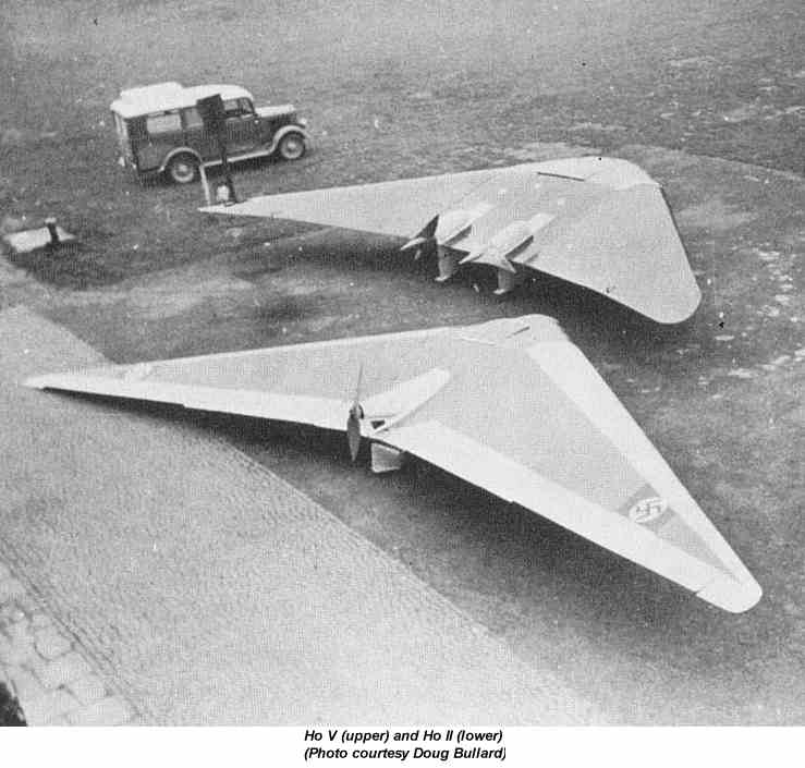
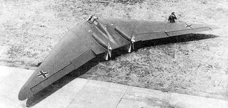
FARNBOROUGH HANTS
The Horten Tailless Aircraft
by K.G. Wilkinson, B.Sc. D.I.C.

Horten V, VI, and VII


3.7  Horten V

General

     The H 
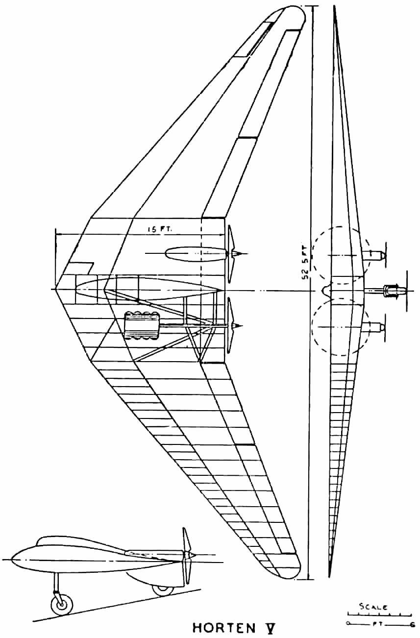
V was designed form the outset as a powered aircraft using two Hirth H.M. 60 R motors driving oppositely rotating propellers.  It has a span of 52.5 feet, aspect ratio of 6:1, and a quarter chord sweepback of 
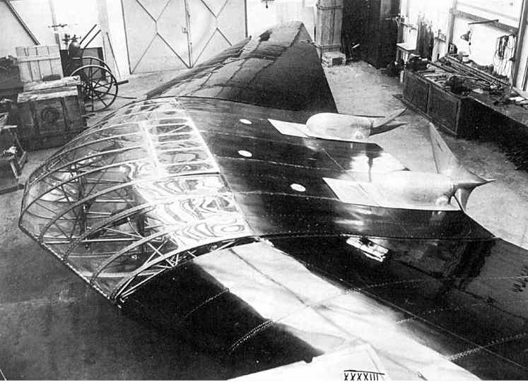
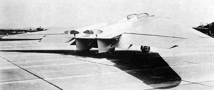
32 degrees.  Engines were completely buried and drove propellers on extension shafts raised relative to the engine crankshaft and driven through a reduction gear.  The undercarriage was of fixed tricycle type with castoring nose wheel and trousered main wheels.  The nose wheel actually too 55% of the static weight when on level ground.
     Three examples were built.  The first, built at Ostheim in 1936 was constructed of plastic material with riveted sheet plastic covering.  Pilot and passenger were contained entirely in the wing contour and the nose wheel was retractable.  This aircraft crashed on its first flight, due mainly to its unorthodox waggle-tip control.  The second version used more normal control methods and conventional construction, it was started in 1937 and flew successfully.  In 1941 it was completely rebuilt (Fig. 12, 13a, 13b & 13c) as a single-seater, but retained the same control system.

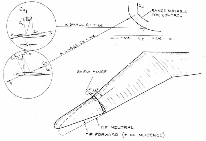
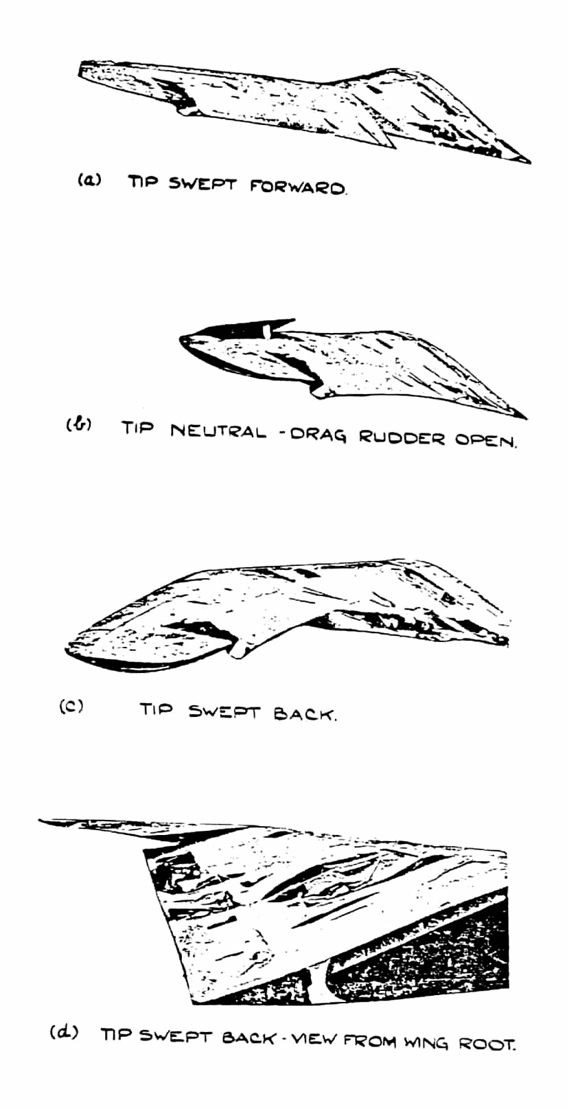
Controls

     In its original form the H V was fitted with waggle tip control (Fig. 26) in which the fore and aft sweep of the wing tips was geared to the stick, producing incidence change by a skew hinge arrangement similar to the illustrated in Figs. 26 & 27.  The aircraft crashed on it first flight due to the control taking charge after a bounce during landing.  The reason for the accident was obscured by a failure of one engine but the control system was not regarded as satisfactory by the Hortens who later developed the idea further on an H III.  They considered that damping is necessary to prevent the tips oscillating under suddenly applied acceleration (as occur during take off and landing).
     The second aircraft in both its forms had a two stage elevon control rather similar to the H III.  Maximum control deflections were as follows:

Control Column                                                   Port              Starboard
    Position                                                      Outer Inner       Outer Inner
Fully left                                                          -20      -2             +20    +2
Fully forward                                                  +5   +30             +30    +5
Fully back                                                       -40      -5                -5    -40

       The outer control flaps had a 20% Frise nose and assymmetrically geared tabe to compensate the non linear moment characteristics of the nose balance.  The inner flap pair had round noses.
       Split trailing edge flaps were fitted to the center section, the flap between the engines lowering to 60° and the part outboard to 45°.  The inner elevon flaps dropped to 30° when the center section flaps were lowered and still operated as elevons about this new zero position.  The idea of using graded flap deflections originated from a hunch of the Hortens that the sudden discontinuity and greater spanwise flow with ungraded flaps might cause stability and control troubles.  They later found that this fear was unfounded and gave up the graded deflection principle.
     Rudder control on the second two aircraft was by split nose flaps on the H III pattern (Fig. 3, ed. – not reproducible).

Flying Characteristics

     A great deal of flying was done on the second and third H V’s, including about twenty flights on the latter in 1943 by Prof. Stuper of A.V.A. Gottingen.  We questioned him extensively about his impressions of the aircraft (Sept. 21, 1945), because it was the most recent Horten product he had flown.  The Hortens themselves had lost interest in the H V because later designs incorporated many improvements.  Stuper has also flown the H IIId with Walter Mikron engine.
      Tests at A.V.A. were undertaken at the request of D.V.L. who wanted information on single engine characteristics and an unbiased comparison between tailless and conventional handling qualities.  Stuper’s comments were as follows:

Stability

      Longitudinal dynamic stability was good and no fundamental different from a conventional aircraft could be noticed.  In rough air he thought it had a more abrupt pitch response than normal, which was only a disadvantage if gun platform steadiness was needed.  (Walter Horten thought this effect might be due to the low wing loading (6 lb/sq.ft.) on the H V and Stuper agreed that this might be so).
     Lateral stability appeared satisfactory.  No tendency to “dutch roll” instability was found and no arratic changes of heading due to low Nv and Yv were noticeable.  Stuper was in fact expecting trouble from this source but failed completely to find any.  He added that his impressions were purely qualitative as they had no time to instrument the aircraft.

Controls

     Controls were light and effective, with the exception of the rudder, which was heavy and not effective enough.  Aileron was heavier than the elevator “in the ratio 4:3”.  With the stick back, aileron movement was restricted, which Stuper thought a bad point since plenty of aileron was useful in an approach in gusty weather.  The aircraft was in trim virtually over the whole speed range without movement of the elevator trimmer.  When flaps were lowered there was a slight nose heavy tendency which could easily be held.
     Summing up, Stuper said that aileron and elevator control were quite normal but rudder control needed improvement.

Stall

     Behavior at the stall (flaps down) was very satisfactory, the nose dropped gently and the aircraft gained speed.  Wing dropping could be induced if the aircraft was stalled in a yawed attitude but normally the wings remained level and ailerons still effective, thought restricted in movement.  The stall was reached with the stick not quite fully back; only one CG position was tested.  Stalling speed was about 70 kph.

Single Engine Flight

     Flight on one engine was possible, without rudder, at 120 kph by flying  with 10 degrees of bank and 80% aileron.  Rudders were not used much because they were so heavy, although Walter Horten claimed that at 130 kph single engine flight could be maintained on rudder only (engine nearly at full power) if the pilot was strong enough.

Landing and Take-off

     Ground maneuvering was easy using throttles and wheel brakes.  During take-off the aircraft could quite easily be kept straight until the drag rudders became effective, and flew itself off the ground without assistance from the pilot - in fact it made very little difference what the pilot did with the controls during take-off.  There was no tendency to bounce during the ground run.  R.L.M. require that for normal tricycles, it should be possible to left the nose wheel before take-off speed is reached; Walter Horten thought this was unnecessary if the aircraft would fly itself off.  Landing was quite straightforward and normally the aircraft settled down on all wheels at once.  Stuper thought it was not possible to land on the main wheels first because the ground incidence was too high.

Baulked Landing

     Stuper had done some tests of take-off performance with flaps down, which resulted in his flying into a hanger and terminating the A.V.A.test programme.  Apparently he landed and immediately (Walter Horten said not immediately) opened up to take-off again - after 530 meters he was 8 meters high and at that point entered the hanger.  The airborne distance was about 150 meters.
      Although the split flaps in front of the propellers caused poor thrust, there were apparently no vibration problems.
     Summarizing his impressions on the H V, Stuper said that it was hardly fair to compare ti with conventional aircraft with many years more development behind them but it was nevertheless, a good example of tailless design and a perfectly practical aeroplane - if anyone wanted tailless aeroplanes.  His main suggestion for improvement was in the rudder control.


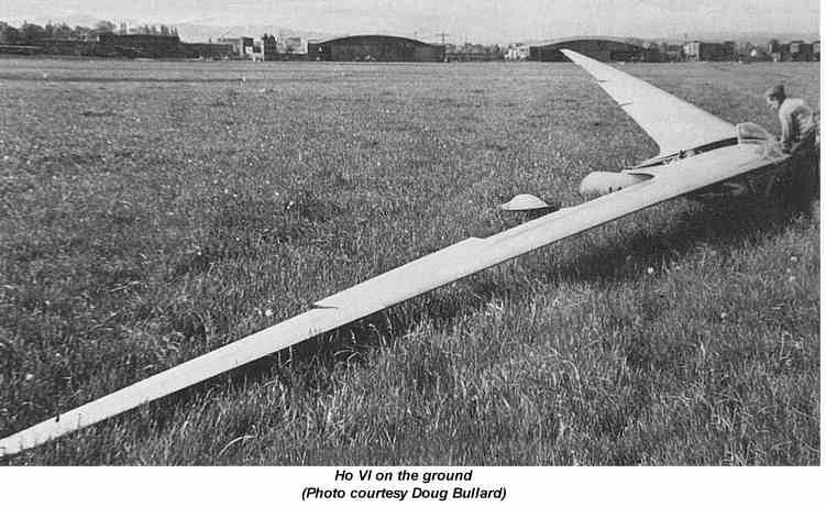
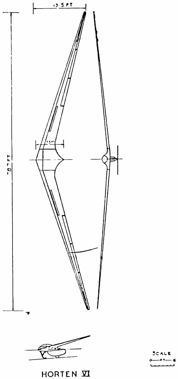
3.8  Horten VI

     In general layout of this aircraft was very similar to the H IV.  The span was increased to 24 m (78.7’) accompanied by a decrease of 5% in wing area, giving an aspect ratio of 32.4.
     The object in building the H VI was to achieve the most efficient high performance sailplane regardless of cost.  Two were built and the first was tested late in 1944.  It was performance tested by the relative sinking speed method previously described, using a calibrated H IV for the second glider.  The Hortens were very pleased because it was better than the D 30 (same span and wing loading) over the whole speed range.
     Aerodynamically there were no new features of special interest compared with the H IV.  Wing sections and control systems remained the same.  The structural design had to be refined in order to get sufficient bending strength in the very thin cantilever.  The main spar was made up of laminations of plain wood and “bignefel” (a compressed impregnated wood) to give extra strength at the root, and a special wing root fitting using four taper pins in place of the normal two was devised to distribute the concentrated loads at the root.  The torsion box design was modified also to increase the wing torsional stiffness, since at high speed it had been found that an unstable short period longitudinal oscillation, involving wing twist, could develop.  The speed at which the damping of this oscillation became zero on the  H VI was found to be about 180 kph.
     The H VI is of interest only as a high performance sailplane for record breaking purposes.  It is too costly and difficult to handle for general use.
     The second aircraft of this type to built was found intact, by the writer, near Horsfeld; the first aircraft was found destroyed neat Gottingen, where it had been flying.


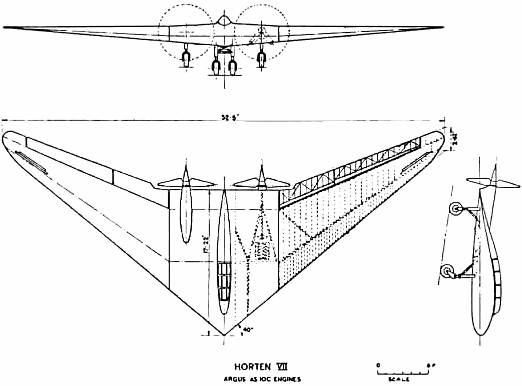
3.9  Horten VII

General

     The H VII was projected in 1938 and the first of the type was built by Peschke at Minden in 1943.  It bears a general resemblance to the modified H V in layout and control design and used the same outer wing panels:  the span was the same (16m) the sweepback slightly greater (34 degrees) and aspect ratio 5.8 instead of 6.1.  Its function seems to have been that of a high speed two-seater commun- ications aeroplane and trainer 
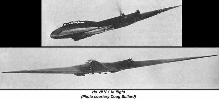
for tailless pilots.  Engines were Argus AS 10 C of 240 hp. Fig. 15 shows the general arrangement and Fig 16 (ed. - not reproducible) gives some pictures of it on the ground and in flight.
      Altogether two were completed and flown and a third was nearing completion at Minden when the district was occupied by the Allies.  Two aircraft were damaged beyond repair and the third fell into Russian hands at Eilenburg.

Controls

     Single stage elevon control was used on the H VII with 25% Frise nose and geared tab.  Inboard of the elevons was a plain flap and in the middle trailing edge split flaps extending for the full width of the center section.  Initially the graded flap angle principle was used, the part between the engines opening to 60 degrees, between the engine and the outer wing panels to 45 degrees, and the plain flap on the wing lowering to 20 degrees.  When R.L.M. ordered the design in quantity however they asked for it to be simplified and for landing speed to be raised to give pilots more realistic training for high speed aircraft.  The plain flap was accordingly locked up on the second aircraft and omitted altogether on the series production model.
     Plug spoiler drag rudders of the H IV type (Fig. 7, ed. - not reproducible) were used on the first aircraft.  These tended to suck open and had to be held closed by springs.  They were not very satisfactory from the point of view of control forces and feel, and after about 10 flights they were scrapped and replaced by a new “trafficator” design.  This was simply a bar which projected 40 cm in a spanwise direction from the wing tip when rudder was applied and retracted flush with the wing surface when not in use.  Fig 17 (ed. - not reproducible) shows the rudder in open and closed positions but without the vent holes, which were cut to adjust aerodynamic balance.  The vent holes allowed flow through the bar and deflected the flow sideways to generate a self-closing aerodynamic force.  This was supplemented by a spring loading and the two components adjusted to give satisfactory feel on the rudder bar.  This type of rudder was claimed to be cheap and easy to make and generally more satisfactory then previous designs.

Structure

     This followed normal Horten practice, the center section being of welded tube construction and the wings of single spar wooden construction with ply covering.
     The undercarriage was a completely retractable four-wheel layout, the front wheel pair taking about 50% of the total weight when resting on level ground.
     The constant speed airscrews were driven through extension shafts with a thrust ball bearing and rubber flexible coupling at the engine end and a self aligning ball bearing at the airscrew end mounted on a cantilever form the main structure.

Aerodynamic Design

     Outer wing panels were of the same aerodynamic shape as those of the H V.  At the center line the section was 16% thick with 1.8% camber (zero Cmo) graded to 8% symmetrical tip sections.  Wing twist was 5 degrees; 2 degrees linearly and 3 degrees parabolically distributed.  The aircraft trimmed with elevons neutral at 260 kph (CL = 0.16).

Performance

     The following performance data were quoted by Reimar Horten from memory:

     Flying weight (minimum)                                                           2,900 kg
     Flying weight with full equipment                                            3,200 kg
     Engines 2 x 240 hp Argus AS 10 C (normally aspirated)
     Sea level (crusing speed (180-200 hp per engine)                310 kph
     Sea level (top speed)                                                                    340 kph
     Normal take-off speed                                                                  110 kph
     Ground run                                                                                      250 meters
     Sea level rate of climb at 180 kph (full power)                             7 m/sec.
     Ceiling                                                                                           6,500 meters
     CLmax = 1.2 no flaps
                 = 1.6 with all flaps
     Delta CL due to plain flap was 0.1

Handling Characteristics

     Reimar Horten told us that prior to the first flights b Scheidhauer on the H VII, his brother Walter had supervised the CG’ing of the aircraft ad mistakenly put ballast in the nose because the measurements were made with a steel tape with 10 cm missing from the end.  Scheidhauer’s comments to us were that the aircraft had to be brought in at a minimum speed of 120 kph, with the stick nearly right back, if the nose was to be lifted for the hold off; the aircraft then floated (stick fully back) util 90 kph before touching down.  Normal take-off procedure was to accelerate to 120 kph and then pull the stick back when the aircraft immediately took off and climbed away.  Apparently it could be unstuck at 90 kph by pulling back hard but would not climb until 120 kph had been reached.  It was impossible to stall the aircraft with the CG in this position; the general behavior was said to be “good natured”.
     Walter flew the H VII (with the CG in its correct position) on 30-40 occasions, a total flying time of about 18 hours.  (Scheidhauer’s time was also about 18 hours).  Apparently the change in CG brought the approach speed down to about 100 kph and the aircraft could be touched down on the rear wheels.  It was not certain that a complete stall could be produced in steady flight.  With the stick fully back the aircraft sank on an even keel with fair lateral control.  Lateral control was pleasant, the 25% Frise balance eliminated adverse yaw and virtually enabled flying on two controls.
     Tests with the “trafficator” drag rudder showed that single engine flight could be maintained with half rudder and a little sideslip; turns could be made in level flight against the dead engine.  On one test the pilot was carrying out a single engine approach when he realized that he had stopped the engine supplying the undercarriage hydraulics and could not lower the wheels.  He was able to climb away, start the dead engine and made a normal landing.

..PREVIOUS SECTION................................NEXT SECTION

...3/11/01
DIRECTORY
Back Home...