|
3.10 Horten
VIII
General
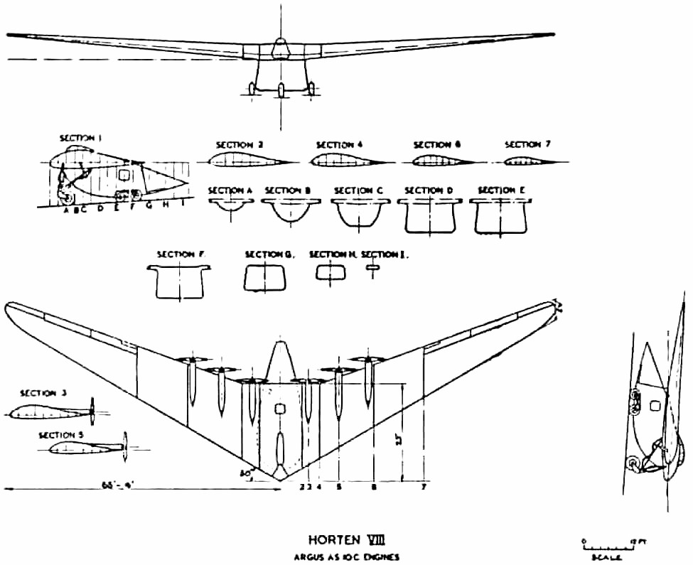
This was to have been
a flying model of a proposed six-engined trans-Atlantic passenger transport
weighing 100,000 kg. The span was to be 40 m with an aspect ratio
of 10 and sweepback of 28°. Power units were six Argus AS 10
C engines.
To make the aircraft
attractive to R.L.M. and thus get backing for the project, the Hortens
added a rear loading cargo carrying body with an internal space approximately
14 x 10 x 6; this was not part of the design for the full size aircraft.
With construction under way, another modification was made (but not disclosed
to R.L.M.). This consisted of removing the nose of the cargo body,
replacing the nose wheel by wheels on either side of the body and putting
a large venturi tube with a 2m x 2.7m throat inside to form a flying wind
tunnel. They expected to get about 500 mph airspeed in the throat
combined with low turbulence this they proposed to check by the sphere
drag method. Later they hoped to be able to test models of their
aircraft which could be made of wood because of the absence of dust in
the airstream.
Construction was proceeding
at Gottingen and was 50% complete at the cessation of hostilities.
The steel tube framework for the venturi center section was finished.
Estimated Weight and Performance Figures
Max. all up weight as a wind tunnel
9,000 kg
Max. all up weight as a cargo carrier
Without takeoff assistance
15,000 kg
With rocket assisted
takeoff
20,000 kg
At 23,000 kg the sea level rate of climb at full
power would be zero.
At 9,000 kg rate of climb at 180 kph was expected
to be 6.5 7 m/sec.
Estimated trimmed CLmaxs were
No Flaps
1.4
With Flaps
1.6
CL for Takeoff
1.1
Aerodynamic Design
The design of the wing
and controls was similar to that of the Horten IV. Washout was large,
7°, to give trim without elevator deflection at cruising CL.
Elevons were the three stage type with 35% Frise nose on the outer flap,
and 22% on the middle and inner flaps. Compensating geared tabs which
could also be used a longitudinal trimmers were fitted to the inner flaps.
Maximum control deflections were a follows:
(Note: All figures in degrees)
| .. |
------- |
PORT
|
------- |
--------- |
STARBOARD
|
------ |
| CASE |
OUTER
|
CENTER
|
INNER
|
INNER
|
CENTER
|
OUTER
|
| Stick fwd. & central |
5
|
12
|
15
|
15
|
12
|
5
|
| Stick back & central |
-10
|
-18
|
-10 or -15
|
-10 or -15
|
-18
|
-10
|
| Stick central & to port |
-30
|
-15
|
-8
|
12
|
10
|
5
|
| Stick central & to stbd. |
5
|
10
|
+12
|
-8
|
-15
|
-30
|
Trailing edge split flaps
with a constant chord of 80 cm were to be fitted between the engines.
Drag rudders were of
the H VII trafficator type with vent hole balance plus spring centering.
Projection was about 1 meter.
Wing sections are shown
in Fig. 18. Root thickness is about
16%, with the usual reflexed center-line, graded to an 8% symmetrical tip
section.
Structure
Wing structure was in
seven parts; a welded steel center section with pilot and co-pilots seat
and three outer wooden wing panels per side. The wooden structure
was of single spar D-tube form with subsidiary trailing edge ribs.
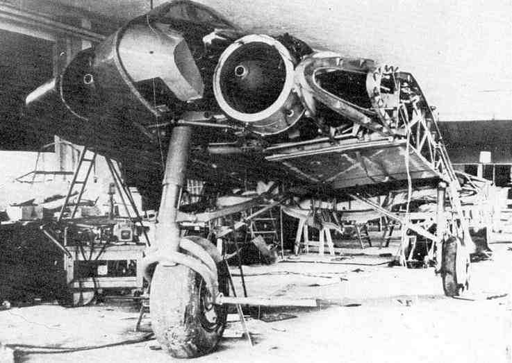
At the factory in Gottingen
the center section was found in a semi-complete state, D-noses for the
inboard wing panels were finished and spars and ply noses for the outer
panels were under construction. Much of the work on components such
as engine bearers, petrol systems, undercarriage etc., had been completed
and the six engines were in crates at the works, with one spare.
Unfortunately all drawings had been taken and many of them seem to have
been buried by Horten employees near Kilenburg, in the Russian sector.
Undercarriage
The fixed main wheels
were arranged in tandem pairs on either side of the fuselage and took 85%
of the static weight of the aircraft. The castering nose wheel was
retractable on the cargo version and had to be mounted on a stalky strut
because of the high wing layout. Static ground incidence was 2.5°.
3.11 Horten
IX
General
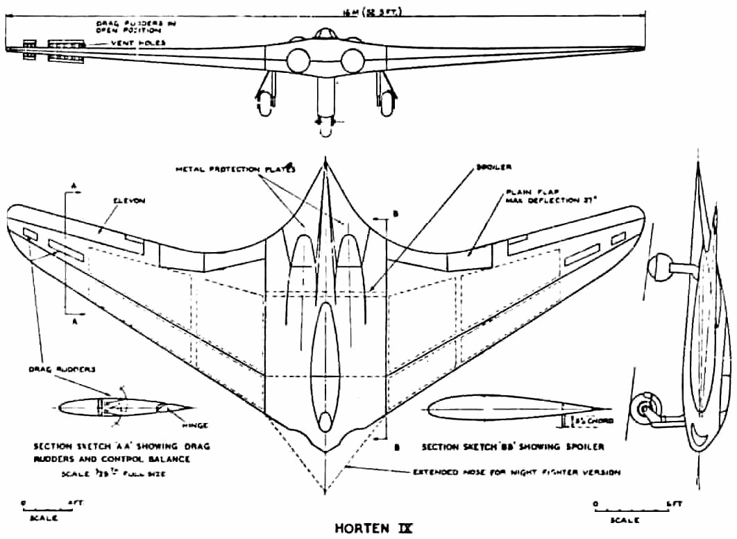
The H IX was a single
seat fighter bomber of 16 m span with twin jet engines, being a further
development of the H V and H VII designs. Fig.
19 is a general arrangement drawing made from a wooden model found
at Gottingen, where the first two of the type were built.
Four aircraft of the
H IX type were started, designated V.1 to V.4. V.1 was the prototype,
designed as a single seater with twin B.M.W. 003 jets, which were not ready
when the airframe was finished. It was accordingly completed as a
glider (Fig. 20) (not reproducible) and extensively test flown.
D.V.L. instrumented it for special directional damping tests to determine
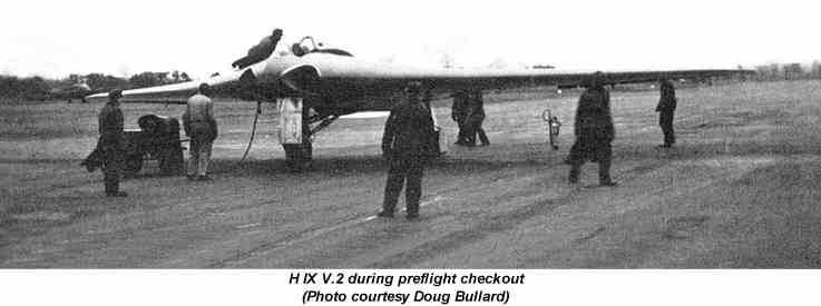
its suitability as a gun platform. V.2 was completed (also at Gottingen)
with two Juno 004 units and did 2-hours flying before crashing during a
single engine landing. The pilot (Ziller) apparently landed short
after misjudging his approach. V.3 was being built by Gotha
at Friedrichsrodal as a prototype of the series production version.
V.4 did not get beyond the project stage but was to be a two-seater night
fighter with an extended nose to house the extra man (Fig. 19) (missing).
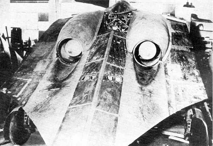
In shape, the H IX was
a pure wing with increased chord at the center to give sufficient thickness
to house the pilot and the jet units, which were placed close together
on either side.
Aerodynamic Design
The H IX started as a
private venture and the Hortens were very anxious to avoid failure so they
avoided aerodynamic experiments wherever possible. A lower sweepback
was used than on the H V and H VII and laminar flow wing sections were
avoided as a potential source of trouble. Wing section at the junction
with the center sections was 14% thick with maximum thickness at 30% and
1.8% zero Cmo camber line. At the centerline thickness
was increased locally to 16% to house the crew. The tip section was
symmetrical and 8% thick. Horten also believed that since the compressibility
cosine correction to drag was based on the sweepback of the maximum thickness
line, the ordinary section would show little disadvantage.
Wing twist was fixed
by consideration of the critical Mach number of the underside of the tip
section at top speed. This gave a maximum washout of 1.8°.
Having fixed this, the CG was located to give trim at CL = 0.3
with elevons neutral. In deciding twist for high speed aircraft,
CD values were considered in relation to local CL
at operational top speed and altitude (10 km in the case of the H IX).
Twist was arranged to give minimum overall drag consistent with trim requirements.
The wing planform was designed to give a stall commencing at 0.3 to 0.4
of the semi-span.
Structure
Wing structure comprised
a main spar and one auxiliary spar or wooden construction with ply covering.
The center section was built up from welded steel tube. Wing tips
were all metal. The undercarriage was completely retractable and
of tricycle type the front wheel folding backwards and the main wheels
inwards. The nose wheel was castering and centered with a roller
cam. When resting on the ground, wing incidence was 7° and the
nose wheel took about 40% of the total weight.
Engine Installation
The jet engines were
installed at -2° to the root chord and exhausted on the upper surface
of the wing at 70% back from the nose (Fig. 22a
& 22b). To protect the wings the
surface was covered with metal plates aft of the jet pipe and cold air
bled from the lower surface of the wing by a forward facing duct and introduced
between the jet and the wing surface. The installation angle was
such that in high speed flight the jest were parallel to the direction
of flight.
Control System
Lateral and longitudinal
control was by single stage elevon control flap with 25% Frise nose and
compensating geared tap balance. (This system was also used on the
H VII, see para. 4.6.) The pilots control column was fitted with
a variable hinge point gadget, and by shifting the whole stick up about
2 the mechanical advantage could be doubled on the elevons for high-speed
flight.
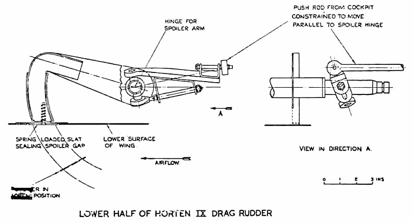
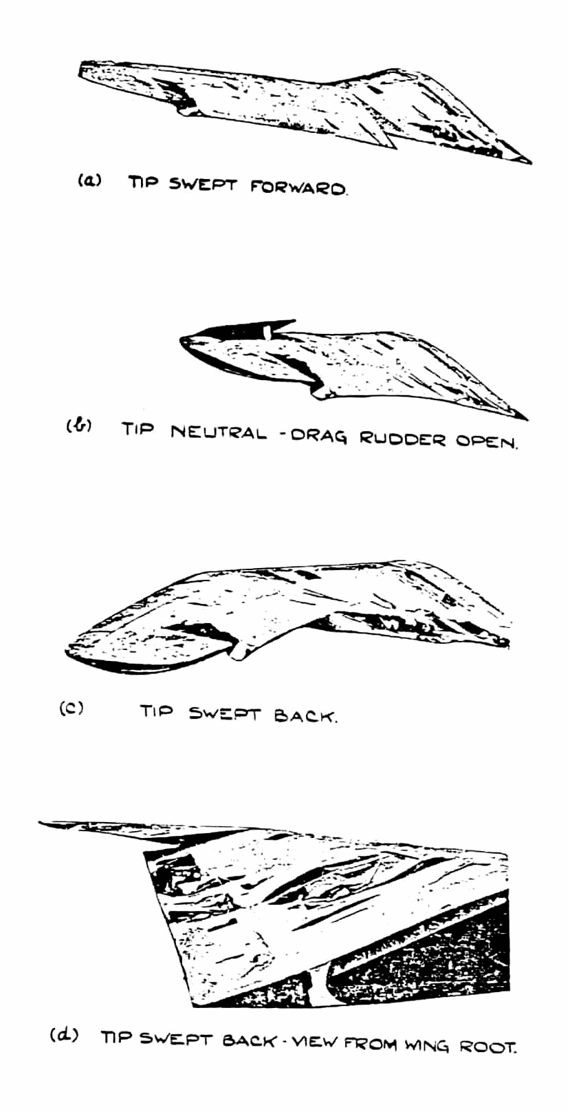
Directional control
was by drag rudders. These were in two sections, slight movements
of the rudder bar opening the small (outboard) section and giving sufficient
control for high speed. At low speeds when courser control was necessary
the large movement also opened the second spoiler, which started moving
when the small one was fully open. By pressing both feet at once,
both sets of spoilers could be operated simultaneously; this was stated
to be a good method of steadying the aircraft on a target when aiming guns.
The Hortens stated that the spoilers caused no buffeting and claimed an
operating force of 1 kg for full rudder, with very little variation in
speed. The operating mechanism is illustrated in Fig.
28. A change was made from the original H VII parallel link system
to improve the control force characteristics. With the new system,
aerodynamic forces could be closely balanced by correct venting of the
spoiler web, leading the main control load to be supplied by a spring.
The cover plate of the spoilers was spring loaded (Fig.
27) to form an effective seal with the rudders closed; this device
was used on most Horten spoiler and dive brake designs.
On further models of
the H IX it was proposed to fit the trafficator type rudder tried experimentally
on the H VII.
Landing flaps consisted
of plain trailing edge flaps (in four sections) on the wings, with a 3%
chord lower surface spoiler running right across the center section, which
functioned as a glide path control. The outer pair of plain flaps
lowered 27° and the inner pair 30° 35° on the glider version
V.1. On V.2 mechanical trouble prevented the inner pair operating
and all flying was done with the outer pair only. The center section
spoiler could be used as a high speed brake and gave 1/3 g at 950 kph.
No dive recovery flap was considered necessary.
Performance
Proper performance tests
were not done on V.2 before its crash and top speed figures were calculated
values, checked by Messerschmitts. The following figures were remembered
by Reimar Horten:
Dimensions
All Up Weight, Including Ammunition and Armor
8,500 kg (18,700 lbs.)
All Up Weight, Excluding Ammunition and Armor
7,500 kg
Wing Area
52 sq.m (566 sq.ft.)
Wing Loading
33 lb./sq.ft.
Fuel (I2 Crude Oil)
2,000 kg (4,400 lbs.)
Performance at 7,500 kg (16,500 lbs.)
Takeoff Run
500 m
Takeoff Speed (10° Flap)
150 kph (95 mph)
(Note:
This corresponds to a CL of 1.30 which is the stated stalling
CL of the aircraft.)
Top Speed (at Sea Level)
950 kph (590 mph)
(CDo estimated to be 0.011)
Calculated ceiling was 16 km (52,000).
Engines would not work above 12 km as the burners went out.
Rate of Climb at Sea Level
22 m/sec (4,300 ft/min)
(Note: This has been checked roughly by
observation.)
In tests against the
Me 262 speeds of 650-700 kph (400-430 mph) were obtained on about 2/3 throttle
opening. This appears to be the only flight test figure available.
Messerschmitt sent performance
calculators to the Horten works to check their estimates. The method
suggested by D.V.L. for getting the sweepback correction to compressibility
drag was to take an area of 0.3 x the root chord squared at the center
section as having no correction applied, and then apply full cosine correction
over the outer wing. Sweepback angle was defined as that of the quarter
chord locus. Test data was available for CDv. for zero
sweepback.
The Messerschmitt method
was to base sweepback on the max t/c locus and to scale Mach number by
the square root cos Ø.
Stability and Control
The H IX V.1 was flown
by Walter Horten, Scheidhauer and Ziller. Scheidhauer did most of
the flying (30 hours) at Oranienberg, Horten and Ziller flew for about
10 hours.
D.V.L. instrumented
the aircraft for drag and directional stability measurements. No
drag results were obtained because of trouble with the instrument installation
apparently an incidence measuring pole was fitted which could be lowered
in flight and glide path angle was obtained from the difference between
attitude and incidence measurements. One day they landed without
retracting the pole. Directional oscillation tests were completed
successfully and an advance report was issued (10 pages of typescript)
by Pinsker and Lugner fo D.V.L.
The essence of the results
was that the lateral oscillation was of abnormally long period about
8 sec. At 250 kph and damped out in about 5 cycles. At low speeds
the oscillation was of dutch roll type but at high speed very little
banking occurred. Many fierce arguments took place at D.V.L. on desirable
directional stability characteristics , the Hortens naturally joining the
long period school of thought. They claimed that the long period
would enable the pilot to damp out any directional swing with rudder and
keep perfectly steady for shooting. It was found that by using both
drag rudders simultaneously when aiming, the aircraft could be kept very
steady with high damping of any residual oscillation.
Lateral control was
apparently quite good with very little adverse yaw.
Longitudinal control
and stability was more like a conventional aircraft than any of the preceding
Horten types and there was complete absence of the longitudinal "wiggle"
usually produced by flying through gusts. Tuft tests were done to
check the stall but the photographs were not good enough for much to be
learned. Handling was said to be good at the stall, the aircraft
sinking on an even keel. There seems to be some doubt, however, as
to whether a full stall had ever taken place since full tests with varying
CG and yaw had not been done. Although the stick was pulled hard
back, the CG may have been too far forward to give a genuine stall.
Directional stability
was said by Scheidhauer to be very good, as good as a normal aircraft.
He did not discuss this statement in detail as he was obviously very hazy
about what he meant by good stability and could give very little precise
information about the type and period of the motion compared with normal
aircraft.
Scheidhauer had flown
the Me 163 as a glider and was obviously very impressed with it; he was
confident enough to do rolls and loops on his first flight. We asked
him how the H IX V.1 compared with the 163; he was reluctant to give an
answer and said the two were not comparable because of the difference in
size. He finally admitted that he preferred the 163 which was more
maneuverable, and a delight to fly (he called it spielzeug).
The H IX V.2 with jet
engines was flown only by Ziller and completed about 2 hours flying before
its crash. This occurred after an engine failure the pilot undershot,
tried to stretch the glide and stalled. One wing must have dropped,
for the aircraft went in sideways and Ziller was killed. Before the
crash a demonstration had been given against an Me 262; Horten said the
H IX proved faster and more maneuverable, with a steeper and faster climb.
In spite of the crash,
Horten thought the single engine performance satisfactory and said the
close spacing of the jets made single engined flying relatively simple.
 ..PREVIOUS
SECTION.............................. ..PREVIOUS
SECTION.............................. ..NEXT
SECTION ..NEXT
SECTION
|