|
3.12 Horten
X
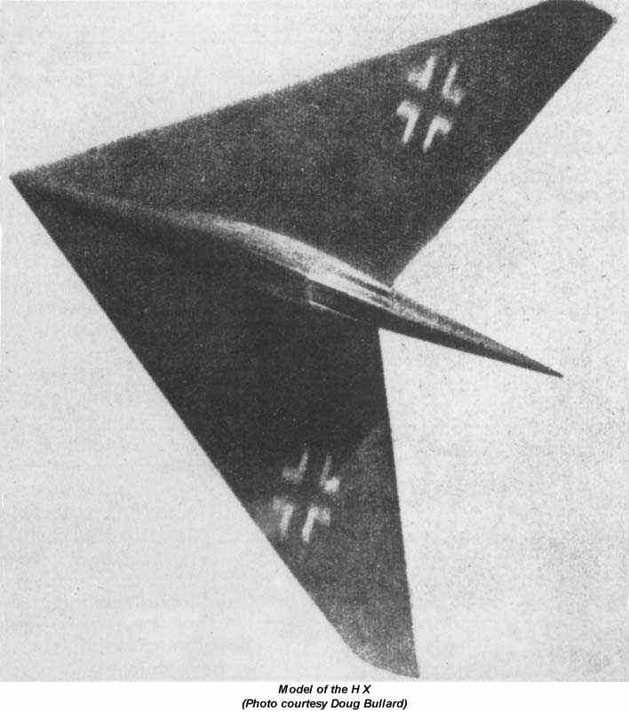
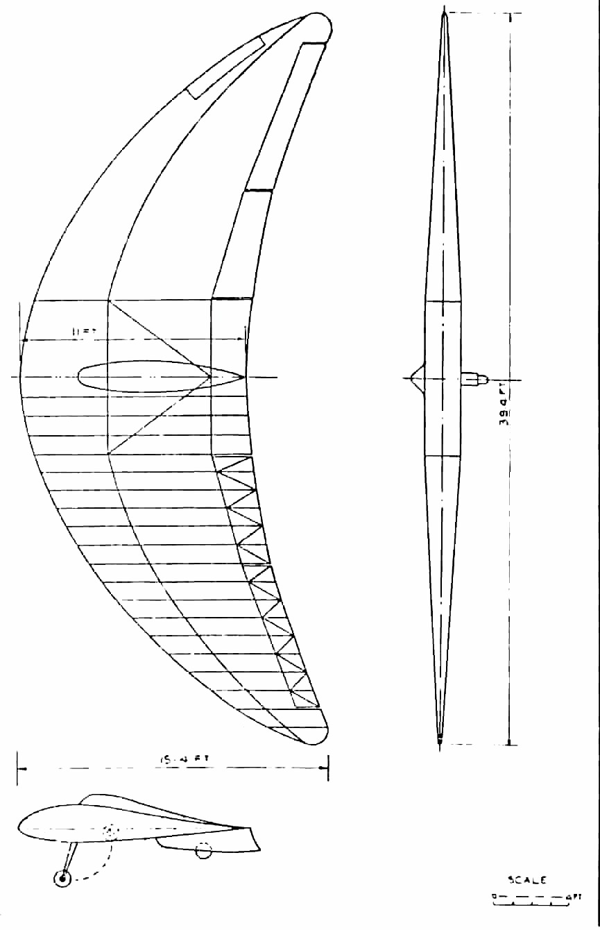
The H
X was a high speed arrow shaped flying wing (Fig. 20, ed. not
reproducible) inspired by Busemanns statement in 1936 of the beneficial
effect of sweepback on delay of the shock stall. This apparently
cheered up the Horten brothers and gave them new proof that they were working
on the right lines.
Initial work on
the H X consisted of experiments with flying models of 10 length weighing
about 8-10 kg. From these they deduced the CG position needed for
satisfactory flight with low aspect ratio and high sweepback, and found
that they got good results with 4° dihedral and no fin area.
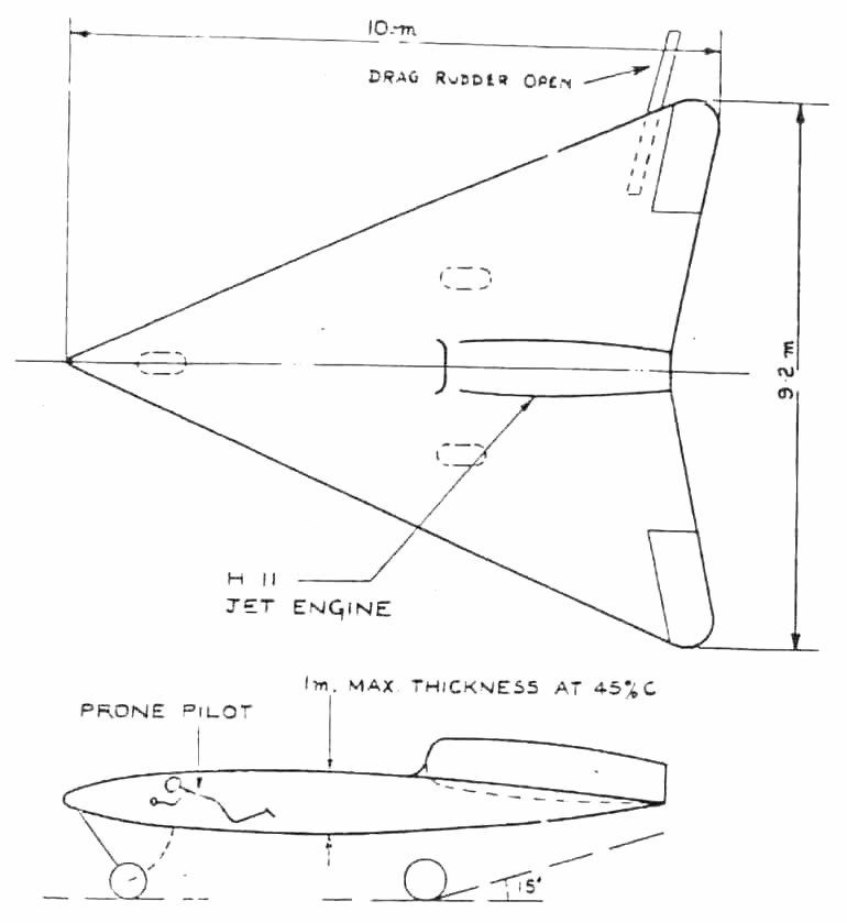
The next step
was a man carrying glider model weighing 400 kg, with the overall dimensions
of Fig. 25. The wing section was a symmetrical D.V.L. low drag type
with maximum thickness at 45% chord. Wing washout was 12° (?),
dihedral 4°. Small Frise nose elevons were fitted but no flaps;
a trimmed CLmax of 0.8 was expected with a stalling incidence
of 20° - 25°. Rudder control was to be by wing tip trafficators.
The undercarriage was of tricycle layout giving zero ground incidence but
clearance for a 15° nose up attitude at takeoff; the front wheel was
to be retractable but the rear wheels fixed.
Work
on the glider H X was in progress at Hersfeld. When the writer visited
the works on June 4, 1945 it was being used as an M.T. servicing depot
and all aircraft components had been dumped in a basement. Only one
wing rib and the main spar could be found. All drawings and calculations
had gone.
After an
exploration of low speed control problems on the glider, the next step
was to have been a power version with an Argus AS 10C pusher engine.
The final development was envisioned as a jet propelled aircraft, with
the same general dimensions, weighing 6-7,000 kg. A single H 11 jet
engine was proposed and a top speed of 1,200 kph was expected with 1,300
kg thrust; the thrust was to be improved to 1,500 kg.
Initial tests
on control effectiveness with high sweep were carried out on the H XIII
to guide the control design for the H X. No ideas for controls on
the final version had emerged but Horten said he intended to stick to Frise
nose balance as long as it would work.
In general appearance
the H X bears resemblance to the Lippisch designs for high speed
and supersonic aircraft, particularly the P 13. Horten said he had
not heard of Lippischs work in Vienna until he came to London. The
main difference in design is that Hortens think a fin unnecessary whereas
Lippisch favors a very large one.
3.13 Horten XI
This was an aerobatic
sailplane of 8 meters span. It was built at Hersfeld and had no features
of special interest.
3.14 Horten
XII
The
H XII was a light side by side two seater with a 100 hp engine. It
was intended as a private owners coupe but R.L.M. were interested in it
as a trainer. The first of the type was built and flown at Gottingen
(where it was found destroyed in June this year) as a glider; work was
also in progress at Kirtorf (sp.) where a mock up of the power center
section was found, badly damaged by fire.
General dimensions were as follows:
Span
10 m
Aspect Ratio
8
Wing Area
32 sp./m (345 sp.ft.)
Leading Edge Sweepback
30°
Weight
700 kg (1,550 lb.)
Wing Loading
2.19 kg/sq.in. (4.5 lb/sq.ft.)
The wing used a Mustang
section at the root graded to a symmetrical section with Mustang fairing
shape at the tip. Washout was 3° - 31/2°.
Elevon controls
were of H VII type with a 20% Frise nose. Plain flaps were fitted
with a H IX center section spoiler and trafficator drag rudders.
The undercarriage was
unusual in having two wheels forward and one main wheel aft taking 60%
of the weight. All three wheels were retractable.
Little flying had been
done, but it was found that the same troubles were arising as on the H
IVb. The laminar flow sections were causing bad tip stalling and
loss of control effectiveness at the stall.
3.15 Horten
XIII
As
part of their program on high sweepback, the Hortens built the . . (ed.
next few words missing) . . to give flight test results on control
. . (ed. next printed line missing) . . section giving a leading
edge sweep of 60°. This increase of sweep reduced the aspect
ratio to four. Control deflections were all doubled to compensate
for the obliquity of the hinge line and the ends of the control flaps trimmed
to run parallel to the new aircraft center line.
The pilot had
to be carried in an underslung nacelle to give him a reasonable view; the
control column was inverted and hung from the roof of the nacelle.
Undercarriage
consisted of a main wheel inset in the nacelle and a fixed nosewheel mounted
on a welded steel tube fork (Fig. 24, ed - not reproducible).
Flying the H XIII
totaled about 10 hours. Trials were interrupted in the middle by
Scheidhauer landing in a barbed wire fence.
CLmax was found to be
0.9, with the stick right back. In this condition the incidence was
larger than expected about 20° 25° instead of 15°, but
Horten thought that the induced drag was not correspondingly increased.
It was thought that the wing was not completely stalled with the stick
hard back because the CG was too far forward.
Control was moderately
satisfactory, but in spite of the increased elevon travel was inclined
to be sluggish. Elevator control particularly was much less sensitive
than on other Horten aircraft.
3.16 Horten XIV
This was
a sports sailplane designed to conform to the 1939 Olympic Games specification.
It was designed for simplicity and ease of production. The first
aircraft was built from sketches and proper drawings for the production
type were made later with slight modifications. Construction was
carried out at Hersfeld.
Span
was 15 m and aspect ratio 16.2. The wing had 23° leading edge sweep
and 8.6° total twist. Sections were 4% camber and 17% thickness
at the root with 10% thick symmetrical tips. Empty weight was 120
kg giving a flying weight of 225 kg.
Controls
consisted of one Frise nose elevon per side with rudders and dive brakes
of H IV design. The glider trimmed at CL=1.0 with elevons
neutral.
The
pilot was put in a prone position as on the H IV and the undercarriage
arrangement was also similar but for the replacement of the rear skid by
a wheel.
Performance was
stated to be:
Maximum Gliding Ratio
1:30 at 70 kph
Minimum Sinking Speed
0.62 m/sec at 55 kph
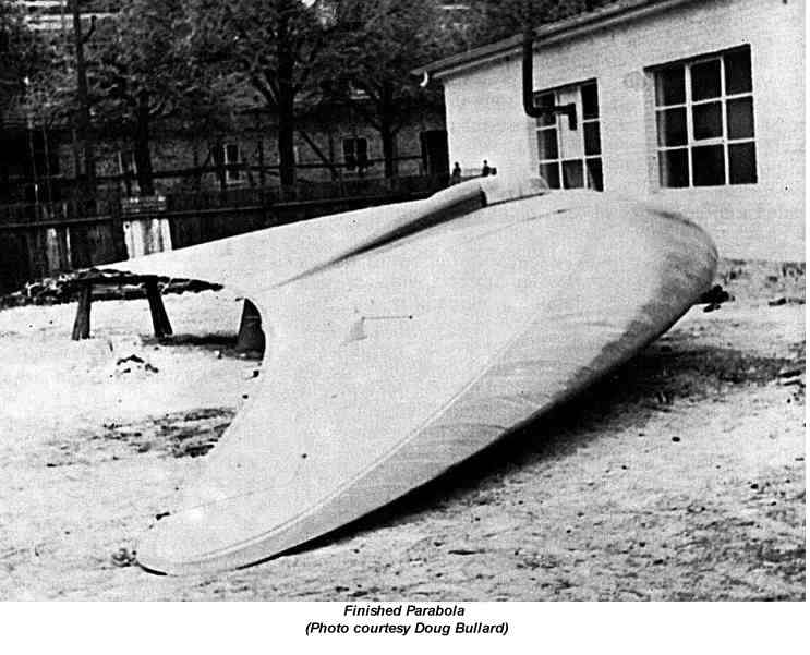
3.17 Horten
Parabola
According to Reimar
Horten this planform is theoretically
the most efficient and has the minimum induced drag. The validity
of the theory is not known. The glider was constructed in a burst
of enthusiasm but proved rather awkward to make because of its curves and
was damaged during transport and never flown.
3.18 Projected
Jet Bomber
In February
1945 a committee under Professor Bock with representatives from Junkers,
Messerschmitt and Horten, deliberated over the optimum design for a 4 jet
engined bomber. Designs by Junkers (Ju 287. A swept forward tailed
aircraft), Messerschmitt (Project 1107 as swept back tailed aircraft),
and Horten (swept back tailless) were considered, and a joint report issued
giving the committees opinion on the best estimate for relative performance.
Junkers published the report.
The
specification to be noted was for 900 kph at 10 km height and a range of
3,000 km using four H 11 jets. According to Horten the committee
decided that his machine, given the same top speed as the others would
have more range and less landing speed. (125 kph against the 175
kph for the others.) Alternatively he could carry 8 tons (metric)
of bombs against the 4 by his competitors for the same range.
The
dimensions of the aircraft were roughly as follows:
Ju and Me
Horten
Span
17-18 m
30 m
Aspect Ratio
5.5
5.5
Wing Loading
500-600 kg/sq,in.
220 kg/sq.in.
Horten aid
the agreed CDo for this aircraft was 0.0078 excluding Mach number correction.
In the structural
design he reckoned to save 6% of the all up weight (spar and rib weight)
compared with the conventional type. He thought the committee a bit
unfair because they insisted on increasing his estimate of structure weight
by about a ton.
All the above
figures were remembered by Horten, who used them as a rough illustration.
They are not accurate.
 ..PREVIOUS
SECTION.............................. ..PREVIOUS
SECTION.............................. ..NEXT
SECTION ..NEXT
SECTION
|