FARNBOROUGH HANTS
The Horten Tailless Aircraft
by K.G. Wilkinson, B.Sc. D.I.C.

How the Hortens Design Their Aircraft


4.  How the Hortens Design Their Aircraft

Introduction

     The Hortens started their careers as aircraft designers in a very practical way, without assistance from highbrow theory.  Early designs were based mainly on what they found satisfactory on a small-scale model.  As time went on Reimar Horten began theoretical investigations of various problems that took his fancy and built up a fairly complex basic design procedure.  Some of his methods seem strange to us and some important aspects he still leaves to “experience” where we tend to trust theory.  The following is a brief account of his methods as related to us at Gottingen in September 1945.

4.1  Wing Section Design

        Wing sections were designed from scratch and were never wind tunnel tested.  The only exception to this rule was the disastrous adoption of the Mustang profile for the H IVb and the H XII.
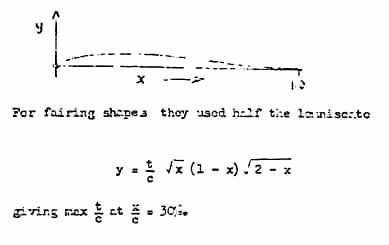
        Camber lines were designed by Birnbaum’s thin aerofoil theory to give zero Cmo.  This gives an equation for the case of 3% maximum camber:

                             0.03 
                   y =  0.1055  x  (1 – x)3

                 dy           d2y
This has  dx  and  dx2  both zero at x = 1 and gives y = max at x = 0.25

        For fairing shapes with maximum thickness at 40% they used a geometrical projection method due to Ringleb.

        To get good stalling characteristics the following criterion was used:

             p/c 
            (t/c)2  = 1.0

      Where p = nose radius
                   c = chord
                    t = maximum thickness

     This criterion is well known and a report by Kawalki of D.V.L. has been published on the subject.

      Wing tip sections are made symmetrical because Horten dislikes the idea of a cambered section  with negative flap deflection at the stall.
       Horten thought that position of the maximum thickness of the wing section had a definite influence on the sweepback that could be used (and vice-versa) due to the influence on lateral flow in the boundary layer.  He suggested that following rough rule for 12% thick sections

            Max Thickness       Maximum Sweep
               Location               (Leading Edge) 

                  30%                            45°
                  40%                            35°
                  50%                            20°

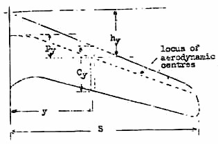
      This rule was based on his experience of the flying qualities of aircraft so far built.

4.2  Calculation of Aerodynamic Centers

        Aerodynamic center was calculated by integration of the product of local loading x distance of the local aerodynamic center behind a convenient spanwise datum.  Load distribution was first calculated by Weissingers method for a sweptback wing.  Details of this were not known but it was apparently a development of Multopp’s method which extended the lifting line theory to take account of chordwise pressure distribution and the influence of this on induced velocity along the span.  Load distribution was used to give values of 

                    d CL  local
                    da     wing.


Local aerodynamic center was assumed to be at 0.25 x n x C from the leading edge, n being a factor representing the departure of the two-dimensional lift curve slope from 2 pi.   n had approximately the following values for different thickness ratios:


     Center of gravity positions were specified by Horten as distances ahead of the above neutral point in terms of a dimension called the “Pfeilmass”.  The Pfeilmass is a measure of the fore and aft dimension of the wing and is defined by:

(ed. – top line of equation is Py dy.)

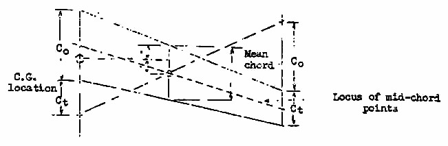
Py is the fore and aft distance between the aerodynamic center of the center section and the aerodynamic center at the general point y.

4.3  Fixing the Layout

Preliminary Determination of CG Position

     As a first approximation Horten used the following graphical contstruction to give a mean chord and mean quarter chord point.

     The first approximation to the CG position was taken as the man quarter chord point defined as above.
      It will be noticed that the mean chord used by Horten is the local chord line passing through the center of area of the half wing.  The above construction does not apply to planforms differing greatly from a trapezium.  The chord length so defined is not the same as that given by s / b.

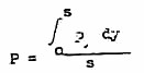
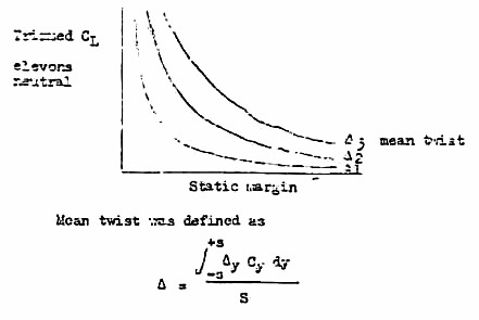
Wing Twist

     The procedure here was to construct curves from which static margin could be chosen if wing twist had been decided, or, more usually, to choose twist for a given static margin, assuming in either case that the desired CL with elevons neutral was known.

                     Where Delta = mean twist
                     Deltay = twist at general point y
                     Cy = chord at general point y
                     S = wing area
                     s = semi span

     Desirable static margins were known from experience and Horten gave the following table (all in % of Pfeilmass) of values for different Horten aircraft.

                                Static Margin
            Type                (% p)                  Comments 

               II                      5% 
              III                      4%                    Normal position
                                       2%                    Minimum for satisfactory longitudinal stability
                                       5%                    For best longitudinal characteristics
                                       3%                    For optimum performance
              IV                     5%                    Normal
                                   6-7%                    Best Handling
          V, VII, IX        2-3% 

        On sailplanes, twist was designed to give elevon neutral trim near to the CL for best gliding angle and on power aircraft trim at cruising CL.  Center section head fairing were found to have an appreciable effect on trim.
        In the case of high speed aircraft, selection of mean twist was farther complicated by the need to avoid local shock stall at high speed.  The method of dealing with this was described in para. 3.11 under “Aerodynamic Design”.
        Twist distribution was determined by the type of aircraft.  For a sailplane, which spends much of its time in circling flight, Horten had developed a theory which enabled twist distribution to be designed so that the glider was in trim laterally and directionally without elevon or rudder deflection.  In the calculation the twist needed to give static equilibrium was found, taking into account variation of incidence, speed, profile and induced drag across the span and assuming straight trailing vortices.
     The answer was a twist of the form

                                                                                
                                                     e = eo ( A  s  + B ( s )3 )

(ed. – missing text about one of the terms being indeterminate.)

         On the H IV for example, twist was designed to give trim in a 45° banked turn at CL = 1.  Incidence difference between the tips was 1° and the twist was

                                                                     y      ( y) ( y)3
                                                      e = 2° (  s  +    s   +   s    )

      An additional aerodynamic twist of 1.1° was added giving an overall designed washout of 7.1°.  The second power term was introduced to satisfy the condition for longitudinal trim (flaps neutral for trimmed flight at 100 kph on the H IV and 140 kph on the H VI).
     On the H III the linear term was much bigger (4°) and the incidence difference between the tips 6° in the specified circling condition.
     Torsional deflection of the wing was allowed for in these calculations.
     In addition to the above requirements Horten also designs the combination of taper and twist to ensure that local stalling lift coefficient is first reached at the middle third of the semi span.  Apparently all those conditions can be satisfied simultaneously, the linear term was said to be available mainly for stall control whilst the cubic term gave the required rolling equilibrium.

Sweepback

       Sweepback is governed to some extent by the load being carried, but for low speed aircraft Horten liked to keep leading edge sweepback below 45° to avoid loss of controller power through boundary layer outflow.  For high speed aircraft, high sweepback was an advantage, for besides keeping drag down it prevented over sensitivity of control.

4.4  Control Design

      His calculations of control forces were customary, design was governed by experience.  Aileron performance was however calculated on the H IX.
      The change over from round nosed to Frise nosed controls was made to improve the yawing characteristics with aileron applications.  The subdivision of the flap into two parts enabled differential to be used to improve the favorable yaw with aileron.  The outer Frise nose in this case balanced the round nosed inner flap also.  In the three stage flap, where the outer flap behaved principally as up going aileron, it was possible to alter the relative balance between aileron and elevator (the latter being usually too light relative to the aileron) and produce better harmony of control.  This was aid to be especially important in high aspect ratio sailplanes (or airplanes ling the H VIII) where  the ratio of lateral inertia to longitudinal inertia is high (e.g. this ratio was about 30 on the  H VI compared with 5 on the H IX).  Further questioning revealed that Horten thought lateral inertia important because the initial response (acceleration) when correcting small gust disturbances depended largely on inertia although the final rate of roll was hardly affected.
      Drag rudder design was evolved entirely by flight experiment with no wing tunnel data to help.

4.5  Flight Stability

      Dynamic stability was never investigated theoretically and was not studied very carefully in flight.  Reliance was placed mainly on general impressions of the pilot and we found no evidence of results having been analyzed critically.
     The Hortens were obviously not in the habit of thinking in terms of periods and dampings, and Reimar did not know that lv and nv were for his various designs; dihedral was fixed by experience.
      The “stick force per g” criterion was not used and although elevator angles to trim were considered in the design stage there was no methodical flight check.

4.6  Undercarriage Design

      During the construction of their series of aircraft the Hortens had been forced to try a number of unorthodox undercarriage layouts using 2, 3 and 4 wheels.  The tricycle and four wheel layouts used wheel positions giving a wide range of weight distribution.  The following figures were quoted:

                            Type                                 H IV              H V              H VIII

                  Nose Wheel Reaction               8                   55                 15
                     (% A.U.W.)
                 Main Wheel Reaction              92                   45                 85

     The H VII and H IX also take a large proportion of the weight on the nosewheel – of the order 40-50%.  These heavy nosewheel reactions were combined with large ground incidence to enable the aircraft to fly off the ground.
      According to Horten none of the layouts tested had given any trouble due to porporsing or instability to unstick; he was inclined to dismiss undercarriage design as presenting no problems.

4.7  Stressing

       Horten stated that there were no special requirements for stress calculations on tailless aircraft.  The H IX was designed for a normal acceleration (n) of 7g combined with a safety factor (j) of 1.8.  Other design considerations were as follows:

(a)  Gusts of + 10 m/sec. in a dive at 1100 kph with j = 1.2.  The air was assumed incompressible for this calculation except that  dCL / da  was arbitrarily increased 50% over the incompressible value.  A relieving factor of 0.6 was applied.

(b)  A complete aileron roll (360°) was to be possible at 900 kph at 2500 m. in 4 seconds, including allowance for aero elastic distortion.  This was both a performance and a stressing requirement.

(c)  There were no official aileron reversal requirements but Hortens designed the H IX for a reversal speed of 1.2  x  diving speed (1320 kph) assuming incompressible flow.

      A peculiar feature in the structural design of the H VII was mentioned.  It was stated that the calculated change of trim to cause a 4g dive pull out at diving speed was only 0.3° of elevon, when allowance was made for aero elastic distortion.  This was improved by increasing the ply skin thickness from 1.5 mm to 2.5 mm.  The phenomenon would be more understandable if the torsion component of spar bending had been large but Horten says that this was not included.
      Actual figures quoted were:

                                                                    Elevator Angle
                                                       1.5 mm Ply       2.5 mm Ply

                            Dive                            +3°                +2.5°
                           4g Pullout                 +2.7°                -0.5°

..PREVIOUS SECTION................................NEXT SECTION

...3/11/01
DIRECTORY
Back Home...