|
Longitudinal This seems generally
to have been satisfactory. It is clear that, particularly on their
light aircraft, there was a difference in longitudinal gust response (and
probably also in control response) which seems to have been more sudden
than on a conventional type but this was less marked in the H IX which
had more normal wing loading. The Horten view was that with correct
CG positions there was little important difference. When questioned
about static stick free instability when approaching the stall they thought
it might possibly be present but were sure that stick force reversal did
not occur.
Lateral All their aircraft appear to have had less damping of the lateral oscillation than normal but also a longer period which made it easier for the pilot to damp out disturbances with rudder. This feature is of interest in view of the widely held view in Germany that the period of the lateral oscillation on a high speed fighter (particularly jet propelled) is too short for good gunnery and should be increased if possible to 4 secs. Directional Directional stability would be expected to be indifferent because of the absence of fins. Northrop has found on his aircraft that the low values of nv and yv made it possible to fly with appreciable yaw without the pilot knowing it, and this led to unpleasant characteristics in rough air. Horten, is satisfied with the behavior of his aircraft without fins and Stuper could not find anything to criticize in this dimension of the H V. After about 1 hours flying in the H IV, the impression is that there is definitely something unusual in directional stability and control. It seems possible to fly with considerable yaw and the response to drag rudder is quite different form that of the conventional aircraft to a normal rudder. As yet it is too early to give a full report on these features. 5.2 Behavior at the Stall and Recovery From the Spin Stall Research Besides doing normal
stall tests, Horten did a certain amount of research with wool tufts to
gain insight into the flow changes at the stall. On the H II glider
surface tufts were used and photographed by a camera in the pilots head
fairing. On the H III more extensive tests were done using surface
tufts on one wing and tufts on 2 masts on the other, the stall being photographed
from a Storch flying immediately above. To assist in the interpretation
of the photographs the glider was fitted with a sideslip vane and an A.S.I.
which registered on the upper surface of the wing and appeared in the pictures.
Chordwise lines were painted on the wing to show readily any yaw of the
tufts. This technique proved difficult, particularly for the Storch
pilot, and the photographs were apparently not very good. They did
confirm, however, that the stall started at the middle of the semi span,
and showed the spanwise drift of the boundary layer. The H V and
H IX were also tufted but no pictures were taken. Horten said that
the tufts again showed that the wing tips did not stall and in the case
of the H V the stall was sketched as spreading to the root whilst leaving
the outer 30% of the semi span unstalled.
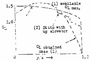
The picture of designed and available CL distribution was as shown. This actually gives slightly better results with CG aft, for, if the extra up elevon required for trim with CG forward decreases the available tip CLmax by Delta CL, then the obtained CL at the tip decreased only by 0.9CL. However, the spanwise flow effect was thought by Horten to be of overriding importance. Tests on the Influence of CG Position on Flying Characteristic Tests on the stalling and spinning of a H III glider were done at the Hornberg with varying CG positions. To start with, weight was added at the back of the center section until the glider was only just flyable. This required 35 kg of ballast (the normal CG position was 2.1 meters behind the center section leading edge, corresponding to 4% pfeilmass static margin). A tube 2 m. long was then put under the center section with a 10 kg sliding weight which was kept forward for takeoff and landing and moved aft for tests at height, giving a static margin of 0 to ½% pfeilmass. Fight characteristics were as follows: (a) CG Forward (10% pfeilmass ahead of neutral point) Stalling and spinning were impossible. (b) CG Normal (4% of pfeilmass ahead of neutral point) Stalling was possible but spinning difficult. Spinning attitude was steep and normal recovery procedure resulted in a steep dive with little sideslip. (c) CG Aft (2% pfeilmass) Normal flying characteristics began to be unpleasant. Longitudinal control became very touchy. (d) Extreme Aft CG (0 to ½% pfeilmass) With this CG position it was only just possible to fly the aircraft because with the stick hard forward it was very near to the stall. Scheidhauer refused to do these tests. The spin was entered with full aileron and rudder, and recovery after two turns was by centralizing aileron and rudder and pushing the stick forward. After one turn the aircraft slid sideways out of the spin with about 60° sideslip and went into a dive. General flying characteristics were most unpleasant. Note: On the H III, the dimension of pfeilmass is about 10% greater than the mean chord, so that static margins can be taken as % mean chord for rough comparison. 5.3 Tests on Laminar Flow In the course of
his work on laminar flow sections Horten carried out some observations
on a 2-seater H III in which transition was detected by a creeping total
head tube connected to a stethoscope, worn by the passenger.
Transition from laminar to turbulent flow was accompanied by a roaring
noise in the earpieces.
CL Transition Point % C Back from Nose
0.1 to 0.2 30% Upper
60% Lower Surface
Chord at the test section was about 3 m. and forward speeds about 10 m/sec. at high CL and 30 m/sec. at low CL. 5.4 CL max None of the Horten designs claimed very high CLmax values. The following table summarizes the maxima stated for various aircraft. Type CLmax Comments
H III
1.3 (no flap)
Measured
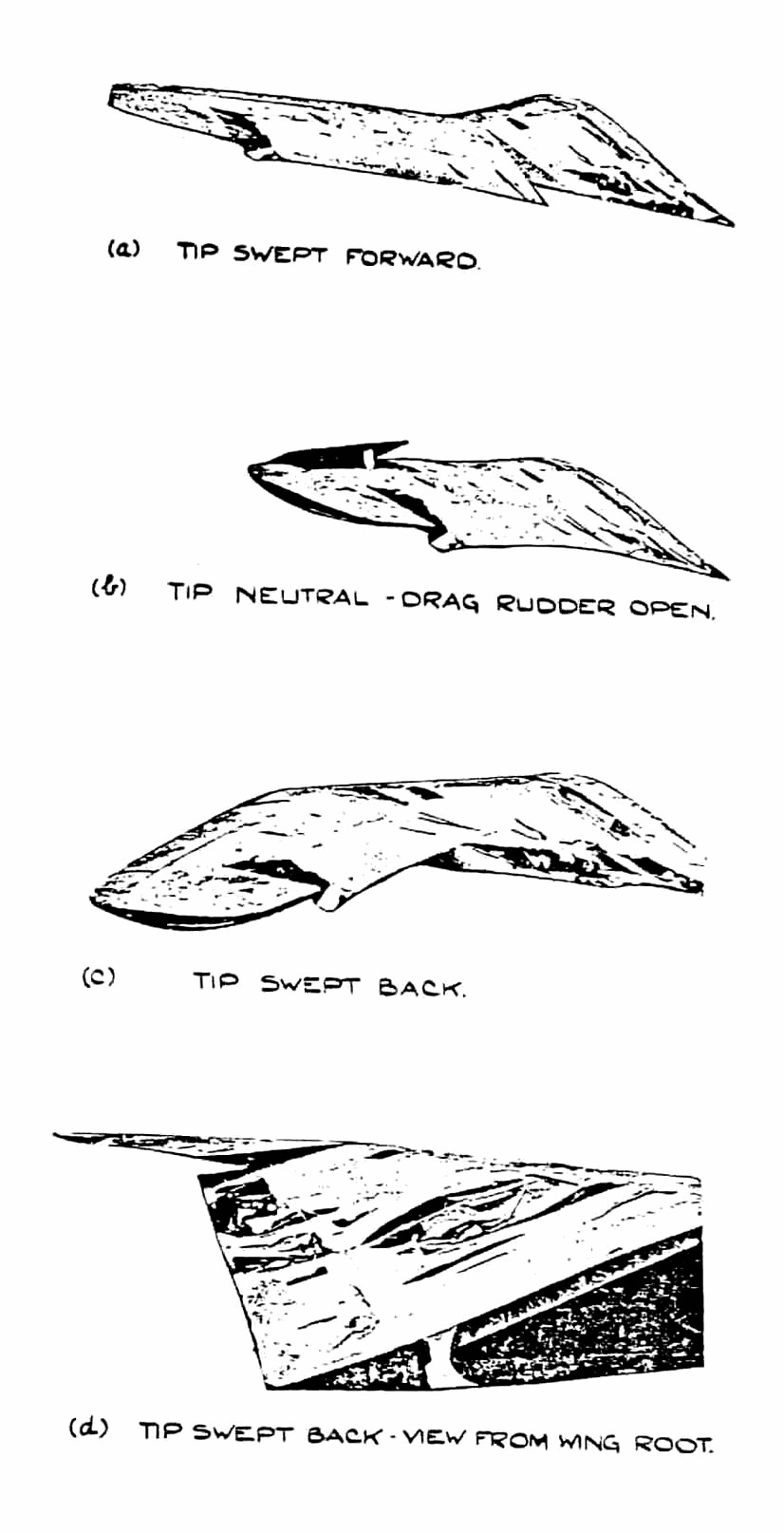
CLmax measurements were made with a swiveling pitot static held below the aircraft on a 4 meter pole which could be retracted for takeoff and landing. 5.5 Waggle Tip Control This
device was first tested, unsuccessfully on the first H V (para. 3.7) and,
later more successfully on a special H III (Fig.
27). The final objective was a stockbrokers aeroplane with
a throttle and rudder bar as the only controls.
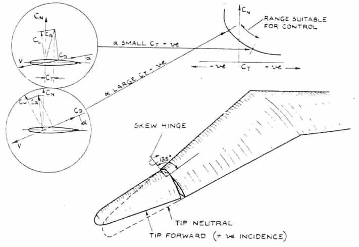
Fig. 26 shows the principle of operation and Fig. 27 the four shots
of the damaged wing of the H III (found at Gottingen) with the waggle tip
in its extreme and mean position. The wing tips were mounted on a
skew hinge so that forward and backward sweep was accomplished respectively
by increase and decrease of incidence.
References Horten, Reimar, Flugzengkonstruktion, Gericht uber die Sitzung Nurflugel flugzeng am 14 April in Berlin (Lilienthal Gesellschaft fur Luftfaburtforschung). Horten, Reimar, Problem of the All-Wing Aircraft (Flugsport, June 10, 1936) Horten, Reimar, Nurflugelflugzeng Horten IV (Flugsport, February 18, 1942) Horten, Reimar, Horten IV Konstruktions ein Zelheiton (sp.) (Flugsport March 31, 1943) Report of C.I.O.S. Team visiting Target No. 25/151 at Bonn near Cologne, March 1945 Attached Drawings Nos. 17890S 17903S inclusive
Circulation D.D.S.R.1
Action copy 1+20
|